
Have you ever cut a sandwich and looked inside to see the cheese and tomato? Section drawings do the same for a building. They slice the building on a drawing so we can see what’s inside.
Sometimes, you have construction drawings showing the stairs and the elevations, but the sections are not on the screen. This means the story is blur, and you need more details. This is where section drawings play their role.
Sections show what plans and elevations can’t. They show vertical relationships, hidden structure, and how water, air, and people move through a building. For general contractors, subcontractors, engineers, and architects, comprehensive sections stop guesswork, reduce RFIs, and keep construction moving smoothly.
This guide gives you the whole playbook. If you want permit-ready, builder-friendly, BIM-connected sections that actually reduce punch lists, read on!
If you want to understand how section drawings fit into the complete construction drawing set, explore our detailed guide on Architectural Drawings
What is a Section Drawing?
Think of a section like slicing a loaf of bread, but the bread is your building. Unlike an elevation (which is an outside view) or a plan (a horizontal slice), a section reveals depth and assembly. A section is a vertical cut through the building that shows internal relationships along that slice, including.
- Floors
- Stairs
- Shafts
- Walls
- The way materials stack.
Simply put, a section drawing…
- Shows vertical dimensions and clearances.
- Explains how materials meet and how loads travel.
- Exposes where services pass through the structure.
- Demonstrates thermal and waterproofing continuity.
How to Place the Cut Plane
Choosing a cut line isn’t random; it’s actually strategic. You must place cuts where the drawing tells the most useful story. Remember that the missed penetrations, surprise junctions, and unclear stair headroom cause the issues. So, put the cut where those risks are concentrated.
Here are some of the pro tips to choose the cut:
- Cut through circulation: Slice the main stair, main corridor, or elevator core.
- Cut through change in level: If the floor steps or mezzanines occur, cut there.
- Cut where structure is complex: Columns, transfer beams, and load-bearing walls deserve a slice.
- Cut to show waterproofing/thermal transitions: Roof-to-wall junctions, window heads, and parapets are high-risk. Therefore, you must cut them.
- Cut to resolve ambiguous plans: If two rooms share a complex junction, place a section to map the interfaces.
Types of Section Drawings
Sections come in sizes and purposes. Each one answers a different question.
1. Site Section Drawings
A site section shows how the building sits on the land. It explains slopes, retaining walls, and how entrances meet grade. This is especially helpful when nothing is flat.
In other words, they show topography, retaining walls, access, and how the building sits in the land. These sections are used when slope, drainage, or road tie-ins matter.
Cutting across the land reveals things plans can’t, like how water flows, how you step into the building, and whether a retaining wall forces a drainage strategy.
Simply put, what you can see on the site sections includes:
- Existing and proposed grade lines (label datum).
- Retaining walls and tie-backs, showing their height and footing within the earth.
- Drainage lines and how the finished grade drains away from the building.
- Approach ramps, driveway tie-ins, sidewalks, and how finished floor levels relate to adjacent roads.
Pro Tips to Create Site Section Drawings
- Always annotate topographic cutlines with spot elevations at critical points.
- Show the groundwater table if it matters to foundations or when basements are present.
- For sloping sites, they include a small inset plan showing where the section cuts the site, which saves them from interpretation errors.
2. Building/Long Section Drawings
A building or long section cuts through the structure from end to end. It shows vertical space, floor heights, stairs, and how people move inside.
How to Build Long Sections
Long sections are the narrative of how a building is used vertically. So create them, covering:
- Floor-to-floor heights, mezzanines, and double-height spaces.
- For stairs and ramps, show landings, headroom, and guardrail/handrail anchorage.
- When you work on shafts and risers, show elevator, mechanical, and service shafts with clear access notes.
- For program zones stacked vertically, include public vs private, and wet vs dry areas.
Pro Tips to Create Long Section Drawings
- Cut where it tells the most, often through the main stair or central corridor. If you have multiple vertical cores, show at least one representative core and a plan showing others.
- Add circulation arrows to show intended flows. They help contractors understand access sequencing.
- Annotate clearances and headroom. Nothing wastes time like rework to increase stair headroom after framing is set.
To understand how site sections integrate with grading, drainage, and full project documentation, review our complete Guide to Construction Documents
3. Wall & Assembly Section Drawings
The wall and assembly sections show material layering, including cladding, cavity, insulation, sheathing, vapor/air barrier, studs, and finishes. These sections are used for thermal and moisture continuity.
All About Wall Sections
Wall sections are where performance and durability live or die. A misunderstood wall section becomes thermal bridges, leaks, or callbacks. However, a reliable wall section has the following qualities:
- Show every layer from exterior cladding to interior finish. That means cavity, insulation, sheathing, structural studs, vapor/air barrier, and interior finish.
- Demonstrate continuity, which means where the air barrier lap, how insulation continue around windows and at junctions, and where flashing is placed.
- Call out fasteners and spacing where relevant – for example, metal cladding fixing at certain centres.
| Layer (Exterior to Interior) | Typical thickness | Function | Notes |
| Cladding (fiber cement/brick) | 8–100 mm | Weather protection | Show cavity/ventilation where required |
| Rain screen/cavity | 20–40 mm | Drainage/vent | Provide weep/flash details |
| Insulation (continuous) | variable | Thermal resistance | R-value target called in spec |
| Sheathing / sheathing membrane | 12–20 mm | Structural & substrate | Show WRB tie-in |
| Air/vapor barrier | thin | Airtightness | Show laps & transitions |
| Stud cavity insulation | 90–140 mm | Thermal & structure | Note cavity batt vs spray |
| Interior finish (gypsum) | 12.5 mm | Finish | Note tolerance and acoustic seals |
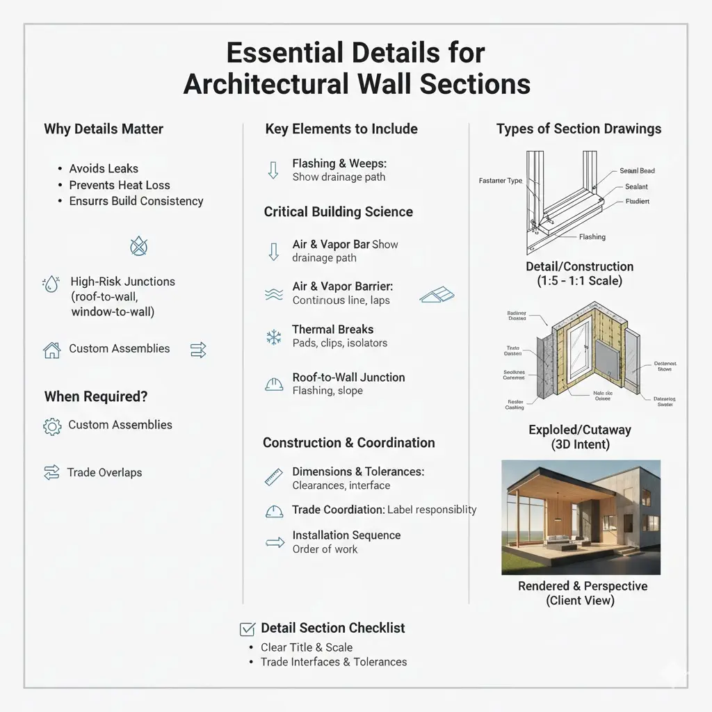
What Details Should be Included in a Wall Section?
4. Flashing & Weeps
Water will find the weak spot, as it always does. That’s why you show flashing and weeps at every penetration, including windows, doors, shelf angles, and cladding changes. Don’t just imply it; you need to draw it. Make the drainage path obvious so no one’s guessing in the field.
5. Air & Vapor Barrier
This is one of those “looks fine until it fails” things. Draw the air and vapor barrier as a continuous line and show exactly how it ties into the foundation, roof, and window head and sill. Call out laps, tapes, and transitions. If the line breaks on paper, it’ll break on site. Guaranteed.
6. Thermal Breaks
Anywhere metal brackets punch through insulation, heat follows. Show how you’re stopping that. Thermal pads, clips, isolators, whatever the system is, spell it out. This is necessary as it’s comfort, energy bills, and callbacks later.
7. Roof-to-wall Junction
You know that moment when everything looks right until the leak shows up. This is where that happens. Show flashing terminations, membrane transitions, slope, and drainage clearly. One good roof-to-wall detail can save years of headaches, time, and money.
8. Dimensions & Tolerances
Call out real clearances for finishes: stone cladding brackets, offsets, backing requirements, all of it. And if you’re dealing with prefabricated panels or curtainwalls, include interface dimensions and tolerance bands. That’s how you avoid field fights and change orders.
9. Trade Coordination
Label where trades meet, including siding contractor, window installer, and waterproofing subcontractor. Be clear about who supplies and who installs critical items like flashings and integrated window membranes. When responsibility is blur, problems multiply. When it’s clear, things move faster.
4. Detail/Construction Section Drawings
They are zoomed-in beats, telling how exactly a window ties into a sill, flashings, sealants, and fasteners. Their scale is measured as 1:5 to 1:1.
In other words, details where intent turns into something labor can actually build. So, if a junction controls water, air, heat, or warranty, you don’t get to stay zoomed out. You have to go in.
Why Detail Sections Matter
Plans explain the idea, and the detail section drawings explain reality. This is where the drawing stops being theoretical and starts avoiding leaks and heat loss. When a detail is clear, everyone builds the same thing, eliminating five different interpretations of it.
When are Detail Section Drawings Required?
Any time failure would be expensive, messy, or hard to argue about later, you need to draw the detail sections. Roof-to-wall, window-to-wall, parapets, and foundation interfaces all live here. The same goes for custom curtainwalls, complex cladding, precast connections, or anywhere multiple trades collide and liability starts getting blurry.
Key Elements of Detail Sections
● High-Risk Junctions
These are the spots where water and air are highly involved. Roof-to-wall transitions, window heads and sills, parapet caps, and foundation walls need their own close-ups. If you ignore these details, the field will figure it out, and that rarely ends well.
● Custom & Non-Standard Assemblies
Any assembly that isn’t straight out of a catalog deserves a detail. Bespoke curtainwall systems, layered cladding, or unusual precast connections need drawings that remove guesswork. If it’s unique to the project, it needs to be uniquely clear.
● Trade Overlapping Points
When waterproofing meets electrical penetrations, or cladding meets window install, things get tense fast. Comprehensive detail sections show exactly where one trade stops and the next starts, avoiding overlapping.
● Tolerances & Field Reality
Buildings aren’t assembled in a lab. Therefore, prefabricated panels, curtainwalls, and cladding systems all need tolerance bands shown on the drawing. If you don’t define the limits, the site will define them for you, which usually adds extra cost.
● How to Streamline the Installation Sequence?
Sometimes the order is everything. Framing, then sheathing, then membrane, and then cladding. A single sequence note can prevent someone from installing a window before the waterproofing is ready.
Detail sections rely on precise drafting standards, which are explained in our guide on Architectural Drafting
Scale & Level of Detail Section Drawings: How Far to Zoom In?
Use 1:5 when you need to show fixings, clearances, and general build-up. Go to 1:1 when precision matters for sealant bead size, fastener type, and edge distances.
What to Look for in Detail Sections?
Look for fastener types and spacing, material thicknesses, and sealant or membrane references. If you’re using a proprietary product, call it out and reference the specification sheet.
A Checklist for Every Detail Section
- Clear, specific detail title
- Reference to where it applies (plan, section, elevation callouts)
- Drawing scale noted and appropriate for the junction
- Complete material callouts with abbreviations and legend
- Material thicknesses and layer order shown
- Fastener type, size, and spacing identified
- Sealant, membrane, or flashing specs referenced
- Proprietary products clearly named with spec references
- Trade interfaces labeled (who supplies, who installs)
- Tolerance ranges and adjustment allowances are called out
- Notes for field variation where movement is expected
- Installation sequence noted if order matters
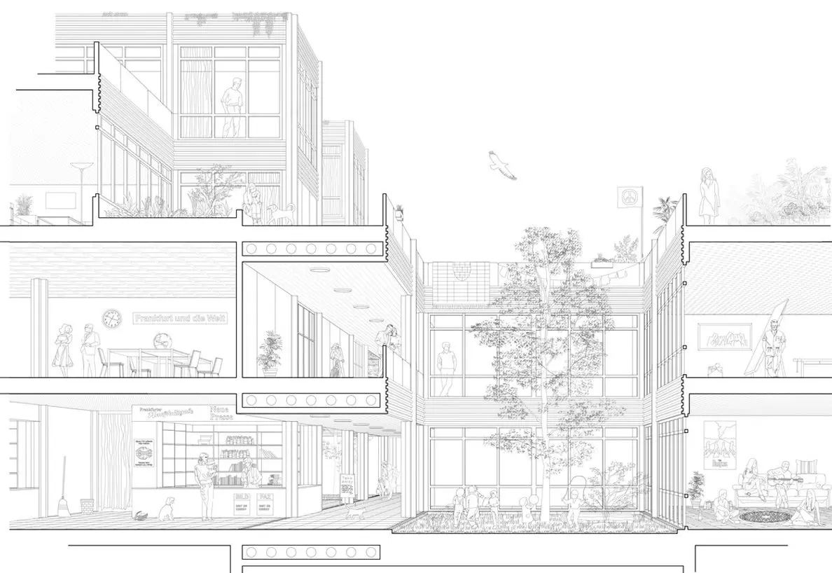
5. Exploded/Cutaway & Rendered Section Drawings
Sometimes a flat section hits a wall. You’re looking at the drawing, and you know there’s more going on than lines can show. That’s when exploded or cutaway sections earn their keep. They help explain 3D relationships without forcing someone to rebuild the assembly mentally. In other words, they are 3D or visually enhanced sections for complex assemblies or client presentations.
When to Use Exploded Section Drawings?
These views shine with complex prefabricated assemblies where parts stack in multiple directions. The same is the case with stairs, including wrapped handrails, layered stringers, and hidden fixings. Mechanical penetrations through layered slabs are another classic case. Routing matters, and a cutaway makes that fast.
Pro Tips to Create Exploded Sections
- Keep exploded views simple.
- Label every component and add a small legend so no one’s guessing.
- Don’t treat these as replacements for construction drawings, as they explain intent, and not dimensions.
- Always include a regular orthographic section nearby.
6. Rendered & Perspective Section Drawings
Use rendered sections for early approvals, client sign-off, or planning presentations. They show daylight, material feel, and scale in a way a line drawing can’t.
Pro Tips to Create Rendered Section Drawings
- Keep a clean line version for the permit set.
- Renders are a supplement, not the build document.
- Use neutral lighting and honest material cues because clarity beats photorealism every time.
- Don’t hide missing details behind pixels.
- For files, deliver high-res PNG/JPEG at 300 dpi for print, and include a vector line PDF for contractors.
- Also, save layered files so you can swap materials without a full redo.
Comparison of All Types of Section Drawings
| Type | Scale range | Primary use |
| Site section | 1:500–1:200 | Topography, retaining, drainage |
| Building/long section | 1:200–1:100 | Vertical circulation, zoning |
| Wall/assembly | 1:50–1:10 | Material continuity, insulation |
| Detail/construction | 1:5–1:1 | Fastening, flashing, and tolerances |
| Rendered/perspective | Any | Client presentation, marketing |
Section Drawings Scale Selection & Conventions Guide
Scale is the language your drawing speaks. Pick the right voice for the reader and the problem. Below is a compact table you can drop into standards or hand to a junior, and they’ll get it.
| Scale | Best for | What to show | When to pick it |
| 1:500 – 1:200 | Site sections | Topography, road ties, big context | Early site design, planning, and grading dialogs |
| 1:200 – 1:100 | Long/building sections | Circulation, floor relationships, program zones | Program studies permit sections showing egress |
| 1:50 | Typical room/section | Finishes, windows, door swings, furniture | Interior layouts, door/window coordination |
| 1:20 – 1:10 | Wall assemblies | Material stacks, flashing, backing | Construction documents for cladding and walls |
| 1:5 – 1:1 | Fabrication details | Fastener types, sealant bead sizes, and tolerances | Shop drawings and manufacture-level detail |
Pro Tips to Choose the Scale for Section Drawings
- Ask who’s reading the drawing.
- Pick bigger context scales.
- Zoom in to 1:5 or 1:1.
- If in doubt, use a long section at a coarser scale with callouts to detailed sections.
- Avoid over-scaling
3-Tier Line System for Readable Sections
A right section communicates at a single glance. The 3-tier line system gives instant hierarchy, so viewers know what to read first.
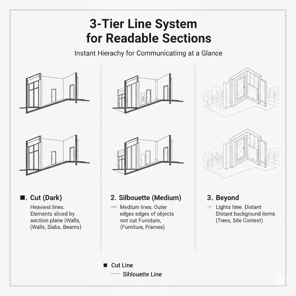
1. Cut (dark)
Cuts (darks), that anchor the drawings, are the heaviest lines for elements sliced by the section plane, covering walls, slabs, beams, and major structures.
2. Silhouette (Medium)
Silhouettes are the medium-weight lines for outer edges and objects that define form but aren’t cut.
3. Beyond (Light)
Beyond are the light, thin lines for distant background items. They show the details on furniture behind the cut, trees, and site context, receding visually.
Pro CAD Tip:
- Assign consistent pen/lineweight values and link them to your plot style.
- Use named layers and verify export settings so lineweights map correctly to printed pens.
- Always print a test plot before issuing documents — on-screen looks lie; paper doesn’t.
Since lineweights, layers, and plot styles are controlled inside CAD files, our guide on What Are CAD Files explains how these settings are stored and exported correctly:
How to Draft Readable Poche & Hatch in Section Drawings?
Poche and hatching give your section depth and clarity. So, cover them well, so they show what’s solid, what’s void, and what material each part is.
Why does Poche Matter in Sections?
Poche are the filled or hatched areas where the cut plane slices the building. They anchor the drawing and tell the reliability of drafts. In complex assemblies, a clear poche stops the plan from turning into a confusing web of lines. Think of it as the silhouette, showing that the targted part is carrying the load.
How to Draft Hatching in Section Drawings?
- Use simple, consistent patterns. Repetition builds quick recognition.
- Avoid dense hatches that print as black; they hide details.
- Reserve standard patterns for common materials, like concrete, masonry, steel, and insulation. Also, cross-reference each pattern in your office legend.
- For unusual materials, create a single, clearly labeled custom pattern, and add it to the legend.
Do’s & Don’ts for Poche & Hatching in Sections
| Do’s | Dont’s |
|
|
Hatching Details for Key Materials
| Material | Suggested pattern | Pen weight |
| Concrete | Diagonal 45° hatch | 0.50 |
| Masonry | Dense cross-hatch | 0.50 |
| Insulation | Dot or light cross | 0.25 |
| Steel | Parallel thin lines | 0.35 |
| Wood | Diagonal spaced lines | 0.35 |
How to Meet Standard Line Weights, Pen Settings & Plotting Rules in Section Drawings?
A right section is what looks right: Line weight must give hierarchy as it tells the eye where to stop and what to read first. Similarly, if you get the pens wrong, your drawing becomes noise. Therefore, it is essential to get them right so that the drawings explain themselves.
Why Line Weights Matter in Section Drawings?
Weight separates cut from contour from background. That separation saves reviewers time, reduces questions, and makes the drawing buildable.
Below is the standard line-weight table, which you can use as a starting point.
| Element | Recommended pen/line weight (mm) |
| Cut elements (walls, slabs, beams) | 0.7 – 1.0 |
| Silhouette (outer edges, facades) | 0.45 – 0.6 |
| Beyond/background objects | 0.13 – 0.25 |
| Hatches & material patterns | 0.25 – 0.35 |
| Grid, dimensions, annotations | 0.13 – 0.25 |
CAD Tips to Make Plots Predictable
- Map lineweights to CTB/STB (plot style) and paper test.
- Prefer vector PDFs for crisp lines; raster can blur thin strokes.
- Use named layers and consistent lineweight assignments.
- Export a checked, printed sample before issuing the set.
Hand-Drawn Pro Tips to Keep Drafting Consistent
- Carry three pens: thick, medium, thin.
- Thick for cuts, medium for silhouettes, thin for details and notes.
- Use rulers and templates; consistency reads as professionalism.
How to Annotate & Label Section Drawings?
Good annotations are buildable. Therefore, it is beneficial to keep them short, unequivocal, and actionable.
● Ideal Annotation Hierarchy
- Start with the basics, like a clear title or identifier, so everyone knows what this section is.
- Next, call out the key dimensions, covering floor-to-floor, headroom, and critical clearances.
- Tag materials and point the reader to your legend or specifications.
- Finish with any special instructions. That order answers the questions people always ask first.
● Leader & Callout Rules
Keep leaders accurate by ensuring that they don’t cross the section lines, keep them short, and use a single leader head per callout when possible. Be consistent with punctuation and pick full-sentence notes or fragments.
● Avoid Clutter
If twenty window heads are identical, use a keyed note instead of repeating the same paragraph because the same text leads to less confusion and conflicts. Additionally, if a note saves a site visit, it’s worth writing.
For consultants who receive drawings in PDF format, our PDF to DWG Converter guide shows how to preserve lineweights, layers, and scales during conversion
How to Set Section Markers & Cutting-Plane Conventions
Where you cut on a plan is where confusion starts. A clear marker doesn’t just show a line; however, it tells the reader which way to look, which sheet to go to, and whether the cut continues. Therefore, you must follow that to stay away from issues.
Ideal Marker Rules for Section Drawings
- Use a clear symbol with arrowheads showing the direction of view.
- Label the marker (e.g., SECTION A–A) and include the sheet reference (e.g., SEE S-12).
- If the cut wraps or continues, add a short leader note: “continues around corner → see A-6.”
- Make markers legible at print scale, avoiding tiny icons that disappear on A1.
- Put markers on a named layer, use a bold dashed cut line for the plane, and set a printable pen weight so arrows and text stay readable.
- If the section spans sheets, show match lines and a brief continuity note right on the plan.
How to Set Dimensions in Section Drawings
Sections are where vertical info lives, so you must get the dimensions right so that the reviewers, fabricators, and site labor all stop guessing.
What to Show in the Section’s Dimensions
- Show floor-to-floor heights. It’s the backbone.
- Add finished floor to finished ceiling (or underside of structure) where it matters.
- Call out headroom clearances for stairs and corridors.
- Don’t forget parapet and parapet-cap heights, and any critical interface heights like sills, handrails, and guardrails.
Section Drawing’s Dimensioning Tips
- Use a single datum and show it on the section and title block while ensuring consistency.
- Don’t mix metric and imperial in one file. Go with the single one.
- For stairs: show rise, run, and a headroom dimension along the stair travel path (not just a side note).
- Call out tolerances separately, including structural tolerances and finishing tolerances. Be clear about which applies where.
- Put important vertical dims near the element they control.
How to Do Section Numbering, Indexing & Sheet Organization?
Once a project grows, memory stops working. People don’t remember where a section is. Clear numbering and indexing are what keep them from guessing.
How to Number Sections to Avoid Misreads?
Use a consistent system and stick to it. Either pair a section ID with its sheet number (Section S-01 on A-12) or use a discipline-based format like A-SEC-01 for architectural sections. What matters isn’t the format; however, it’s consistency. If the system changes mid-set, confusion follows fast.
How to Build a Section Index?
Include a dedicated index sheet listing every section. Add the section title, sheet number, and a small plan thumbnail or cut-line graphic showing where the section comes from. This turns the index into a map, not just a list.
Pro Tip: Any time a section moves, gets renumbered, or is added, update the index immediately. It’s often the first page subcontractors and reviewers open. If it’s wrong, everything falls.
How to Set Section Schedules, Legends & Hatch Keys?
Consistency is essential in all sections. Schedules, legends, and hatch keys are what keep everything aligned across the set.
- A hatch key maps patterns to materials, eliminating the need for guesswork.
- A section schedule shows where each section lives in the project, its scale, and the sheet reference.
- And a short material legend lists common abbreviations used throughout the set (for example, FC = Fiber Cement).
You must keep them short and consistent for easy scanning.
Why Legends & Schedules Matter?
When the same material shows up in ten sections, it needs to look the same every time. A clear legend stops readers from re-learning your drawing language on every sheet. It also keeps reviewers from second-guessing what they’re seeing.
Pro Tip: Store legends and schedules as a master block or a shared sheet. That way, when something changes, it updates everywhere. Don’t copy-paste static legends, as doing so always leads to errors.
How to Coordinate Sections with Building Structures?
Sections aren’t just about finishes; however, they’re where the building’s backbone shows up. If load paths aren’t clear here, people start making assumptions, and that’s where problems begin.
What Structural Information to Show
- Call out beam and column locations with clear bearing points and support conditions.
- Label beams and reference the structural drawings so there’s no disconnect.
- Show how slabs bear on beams or walls, and note where bearing plates or load-bearing walls are doing the work.
How to Set Penetrations & Openings in Sections?
Sections are the right place to show slab and wall penetrations for ducts, risers, and services. Note required sleeves, edge distances, and any firestopping requirements. If it affects structure or fire rating, it belongs in the section.
Pro Tips to Coordinate with the Structural Engineer
- Reference structural drawings instead of redrawing members.
- Confirm beam, column, and slab locations before finalizing sections.
- Coordinate bearing points and load paths early.
- Verify penetration sizes and locations for ducts, risers, and sleeves.
- Check beam flange positions before cladding or facade detailing.
- Align fire-rating requirements at structural interfaces.
- Use clear coordination notes on sections.
- Highlight conflicts early and document resolutions.
- Update sections after structural revisions.
- Never assume structural intent. Rather, confirm it.
Common Mistakes to Avoid During Coordination
- Leaving bearing conditions unclear or unlabeled
- Assuming a wall is load-bearing without confirmation
- Omitting slab, beam, or column references to structural drawings
- Showing penetrations without sleeve or firestopping notes
- Writing vague notes like “beam bears on wall” without a detail reference
- Redrawing structural elements without engineer approval
- Ignoring beam flange locations when detailing facades or cladding
- Missing structural tolerances that affect finishes
- Failing to update sections after structural changes
How to Coordinate Sections with MEP & Building Services
Sections aren’t just about walls and floors; however, they’re where mechanical, electrical, and plumbing (MEP) conflicts show up before construction. Spotting them early saves headaches, rework, and wasted time. To avoid all issues, you must include the following details in your sections:
● Risers & Vertical Runs
They show where pipes, conduits, and ducts travel up and down the building. Include access panels and clear space for maintenance.
● Ceiling Voids
They make sure HVAC ducts, sprinklers, and electrical trays have room. Note any clearance needed for suspended ceilings or dropped soffits.
● Penetrations
They show collars, sleeves, or firestopping at every spot a pipe or conduit passes through a wall, floor, or slab.
Pro Tips to Coordinate Sections With MEP & Building Services
- Hold an early section review workshop with MEP leaders. Walk through vertical runs and potential clashes together.
- For areas with many penetrations, repeat a detail showing firestop and sleeve requirements. This keeps everyone on the same page.
All About Thermal, Waterproofing & Fire-Rated Section Drawings
Sections are where performance gets specified. If your thermal envelope or fire separation is incomplete, you’ll see it here, and so will the reviewer. Here are the functions of each:
1. Thermal Envelope
- Show continuity of insulation and the air barrier. Highlight continuity at corners and around penetrations.
- Detail thermal breaks where metal connects across the insulation plane.
2. Waterproofing
- Show membrane terminations and flashings. Parapet caps, window heads, and sill details are critical points.
- Indicate the slope for draining surfaces and where the water must exit the assembly.
3. Fire-rated systems:
- Show fire-resistance-rated walls, floors, and how penetrations are treated. Call out rating (e.g., 1-hour, 2-hour) and reference tested assemblies or manufacturer details.
- Include firestopping details at service penetrations and indicate required inspection access.
Sections Constructability Checks & QA
Before you send the set to bid or construction, run this checklist. It avoids issues and calls for change orders.
- Confirm all section cut references match the index.
- Verify scale consistency on section sheets.
- Ensure all levels and datum are labeled and match plans.
- Check continuity of air/vapor barrier across sections.
- Confirm flashing/weep locations at all penetrations.
- Confirm dimensions for critical clearances (stairs, corridors).
- Verify structural references and connection notes exist.
- Check that MEP penetrations show sleeves and firestopping.
- Review tolerances and material responsibility notes.
- Print a PDF and review at 100% scale for legibility.
Section Drawings Common Mistakes You Must Avoid
You can spot the common mistakes across projects. Catch them early.
- Overcrowded sections: Too much detail at the wrong scale. Add a callout to a detail sheet to fix that.
- Wrong cut depth: The view includes unrelated background items that clutter the drawing. You can tighten the crop and use beyond elements sparingly to avoid this issue.
- Inconsistent line weights: They lead to significant confusion. Professionals standardize plot styles to avoid that.
- Missing data or mismatched levels: They cause incorrect dimensions. You can fix that by cross-checking level labels with plans.
- No responsibility notes: Contractors argue about who installs flashing. You can insert a short note with clear responsibility to fix this problem.
All About Office Standards, Templates & CAD/BIM Conventions
Consistency saves time. Therefore, you must set clear team rules and enforce them, using the following guidelines:
- Layer naming: Adopt a consistent schema like Discipline-Element-Function (A-WALL-FIN). Keep it short but descriptive.
- Line tables/pen assignments: Map layers to pen weights and test plots. Store them in a master template.
- File naming: Use a scheme like ProjectCode_Discipline_DrawingNumber_v01. Avoid inconsistent abbreviations.
- Title block & revision bubbles: Include clear revision history and sheet numbers.
- Use view templates so sections look consistent across the model.
- Coordinate worksets or worksharing settings, so multiple team members can edit sections without overwriting each other.
Examples of Naming Convention:
- A-SEC-01 — Architectural Section 01
- M-SEC-03 — Mechanical Section 03
Pro Tip: Keep a short “how-to” PDF that shows the five most common file naming and layering conventions.
BIM Workflows for Sections
BIM changes how you make sections because the model is the single source of truth when it’s used well.
Model-Based Vs Drafting Views
- Model-based sections come from actual modeled elements. They’re great for coordination and quantity takeoffs. But you must control visibility and view-depth to avoid issues.
- Drafting views are 2D annotations used when model elements can’t represent a fabrication-specific assembly or when you need an accurate construction detail independent of the model.
Best Practices for BIM Sections
- Set up view templates early by defining scales, lineweights, and visibility variables so section views are consistent.
- Use section families or styles, so you can swap annotation sets quickly for permit vs fabrication.
- Control view depth. Limit beyond distance so the section doesn’t pull in irrelevant background elements.
- Use reference/linked models. Structural and MEP models must be linked and updated before finalizing sections—also, schedule review meetings to swap models and lock coordinates.
- Ensure clean exports. Before exporting DWG or PDF, run a view cleanup script to remove unused tags and temporary objects.
BIM Pitfalls You Must Know
- Don’t rely on automatic sections for complex facades without checking how the system treats curtainwall mullions or panel systems. It is necessary because the model can misrepresent assemblies if families are misconfigured.
- Avoid excessive annotation in model views. Ensure to keep the model geometry pure and put repetitive annotations in drafting views.
How to View Templates & Depth in BIM Tools
View templates are your secret weapon for consistent sections. What to configure in them includes:
- View scale and annotation scale.
- Lineweights mapped to categories.
- View depth and far clip plane settings to limit beyond elements.
- Visibility/graphic overrides to show or hide categories (e.g., furniture off for construction sets).
Where to Use Filters
Use filters for phased work or systems. Using them, you can show existing and demolition differently from new work. Use color or pattern filters for quick visual checks.
Revit How-to?
- Create a view template.
- Set discipline, scale, and annotation settings.
- Adjust the view range and far clip plane.
- Apply to your section view.
Pro Tip: Always test templates on a typical section before rolling out by generating a PDF and checking legibility.
How to Export Sections for Contractors & Permitting?
Key Exporting Rules
- Use vector PDFs for line drawings. They scale cleanly and keep text readable.
- Map lineweights to plot styles and test a 1:1 print.
- Flatten only if you must; keep vector lines when possible. Rasterization blurs small text and lines.
- Embed fonts or convert text to outlines where fonts may not be available.
How to Clean DWG?
- Purge unused layers and styles.
- Lock reference layers or set them to read-only.
- Provide a clean DWG for contractors with an accompanying PDF that is the contract document.
Checklist Before Export
- Are all section callouts readable at the printed scale?
- Is the legend on the same sheet?
- Has the file been reviewed by structure/MEP?
FAQs
How to avoid over-scaling in section drawings?
Don’t try to show every tiny thing on a long building section, since it becomes noise. Use callouts to push fabrication-level info into detail sheets. Keep the main section clear; let the detail do the heavy lifting.
Why is it necessary to set markers in section drawings?
Ambiguous arrows lead to wrong views, and unreadable markers lead to wrong cuts. Clear markers mean the drafter, reviewer, and field team are all looking at the same thing, eliminating confusion and conflict.
What scale should you use for a stair section?
1:50 for general stair sections; use 1:20 or 1:10 for detailed connections and handrail fixings.
Do you need a separate wall section for every wall?
No. Use typical wall sections and reference detail variations where needed. Provide specific wall types for different wall systems.
How do you show an air barrier in a section?
Draw a continuous line at the plane of the barrier, label the material, and show laps and tie-ins at the floor, roof, and openings.
When should sections be model-based in BIM?
Use model-based sections for coordination and quantity takeoffs. Use drafting views for detailed, fabrication-specific drawings not modeled perfectly.
Conclusion
Section drawings are the quiet fix that keeps projects perfect from start to finish. They stop confusion, cut rework, and make sure the building built on site is the building you drew. Do the sections right and everything else gets easier: bids are clearer, labor moves faster, and inspections go smoother.
Want this to happen on your next job? Don’t wait until the first RFI. Get the sections that answer the questions before people ask them!
Get the Permit-Ready, Builder-Friendly Section Drawings Anywhere in the US!
At CAD Drafters, we make section drawings that contractors can build from and that plan reviewers approve. Send us one PDF of your plan set, and we’ll do a free 30-minute review and send back a short report showing the three highest-risk section areas and how to fix them. Contact us now!