
You’re standing at the edge of an excavation pit, dirt in your boots, and you’re trying to picture how the building above will actually sit on the ground. That moment, the one where the whole project either starts clean and predictable or becomes a string of issues and fixes, comes down to one thing: the foundation plan.
This guide walks you through foundation plans. You’ll get the what, why, and how, plus all details inspectors and engineers actually care about. If you want fewer change orders, faster permitting, and a foundation that is ready for construction, stay with us! For more insights and professional drafting services, visit CAD Drafters.
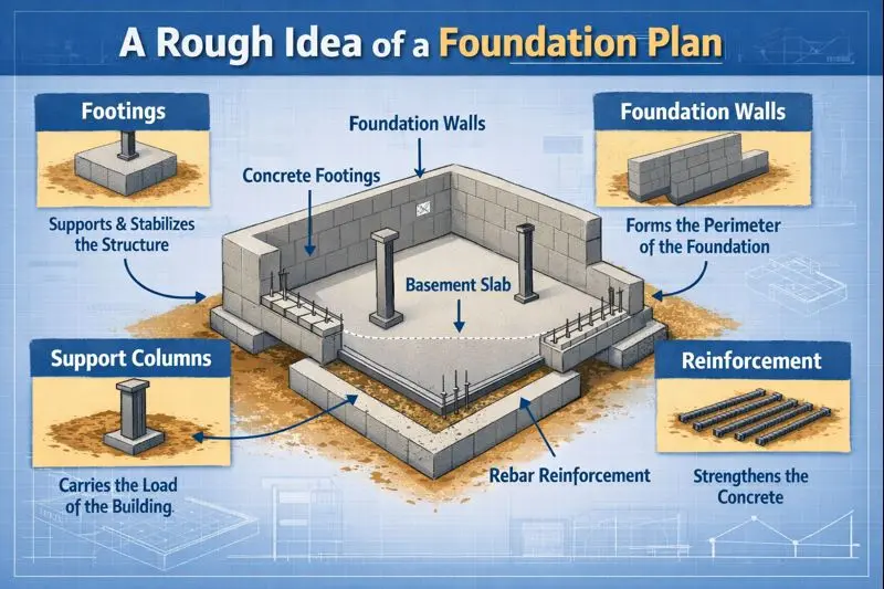
A Rough Idea of a Foundation Plan
A foundation plan is the single document that tells engineers, permitting officials, site contractors, and the inspector where to put footings, how deep they go, what reinforcement to use, and how water and utilities should interact with the base of the building.
One must deal with this carefully because a permit-ready foundation plan reduces guesswork. It eliminates on-site issues, saves time and money. Simply put, spend time and expertise on the foundation plan now so you don’t spend triple later.
What is Actually a Foundation Plan?
A foundation plan is a top-down drawing that shows the footprint of the structure at the foundation level. You can consider it a map of everything that sits below grade: footings, foundation walls, slabs, columns, grades, openings, and critical dimensions. It’s not a rough sketch; however, it’s the authoritative document used for construction and permitting.
What is the Role of a Foundation Plan in Construction
A foundation drawing communicates load paths, footing locations, sizes, and relationships to the rest of the building.
- Engineers use it to ensure structural safety.
- Contractors use it to lay out the work.
- Permit offices use it to validate compliance.
Types of Foundation
1. Basement Foundation
It is a full-depth foundation creating usable below-grade space, and it is typically formed with poured concrete walls or CMU.
Pros & Cons of Basement Foundation
| Pros | Cons |
| Adds living or storage area, simplifies mechanical routing and utility access, and provides robust resistance to settlement. | Higher excavation and waterproofing costs; requires reliable drainage and moisture control; thermal performance can suffer in cold climates unless insulated. |
2. Crawl Space Foundation
This is a shallow foundation that elevates the building slightly above grade; it can be ventilated or sealed/conditioned.
Pros & Cons of Crawl Space Foundation
| Pros | Cons |
| Lower excavation cost, easier access to subfloor utilities, adaptable to uneven sites, and provides a moisture buffer when detailed correctly. | Risk of moisture, pest intrusion, and mold if ventilation or sealing is inadequate; conditioned crawlspaces add insulation and HVAC complexity. |
3. Slab-On-Grade Foundation
These are the concrete slabs poured on compacted fill; options include monolithic slabs or slabs with thickened edge footings for load points.
Pros & Cons of Slab-On-Grade Foundation
| Pros | Cons |
| Lowest cost and fastest to construct, minimal vertical building height lost, well-suited to moderate climates and simple footprints. | Limited access to buried utilities; vulnerable to frost heave unless insulated or deepened; slab repairs can be disruptive. |
What is Included in a Foundation Drawing?
A permit-ready foundation plan drawing needs certain elements. If any are missing, the permit reviewer or the engineer will send them back, which means more time and often more cost.
1. Dimensions
Precise measurements are everything. Exterior and interior footing widths, foundation wall lengths, slab extents, and column locations must be shown and dimensioned. Include gridlines and referenced dimensions so the contractor can set batter boards and layout points without guessing.
Pro Tip: Show both overall dimensions and critical local dimensions for step footings, equipment pads, and penetrations. This reduces RFIs.
2. Materials
Say exactly what goes where.
- Concrete strengths (psi) for footings, slabs, and walls.
- CMU block sizes and strengths if you use CMU walls.
- Soil treatment notes where aggressive soils are present.
- Reference ACI and local standards in the notes so cities see a code anchor.
Don’t assume the contractor will know which grade of concrete to use; make sure you state it in the drawings.
3. Structural Grid
The grid aligns the foundation with the rest of the architectural and structural drawings. Use consistent datums and reference lines across all sets. If the architectural plan uses column lines A–D and 1–7, the foundation plan must match them exactly.
4. Footing Types & Load Paths
Show what footing types you have and where, with a short note on why:
- Isolated/column footings: Point loads from columns.
- Strip/continuous footings: Support bearing walls.
- Combined footings: Used where columns are close together or near property lines.
- Mat/raft foundations: Used for poor soils or heavy loads, show thickness and reinforcement.
Pro Tip: Explain load path succinctly: where the load starts (wall/column), moves to the footing, and transfers to soil. This clarity helps avoid design conflicts later.
5. Footing & Foundation Schedules
Include a footing schedule and a foundation wall schedule. The schedules list sizes, reinforcement, and special notes. Keep them clear and referenced to the plan by tags.
6. Control & Expansion Joints
Slabs move. If you don’t plan joint locations and types (including saw-cut, construction joint, and expansion joint, the slab will crack in inconvenient places. Therefore, it is essential to specify spacing, joint filler types, and saw-cut timing.
7. Insulation & Energy Considerations
Energy codes often require perimeter insulation or slab edge insulation. You need to show insulation locations, thicknesses, R-values, and any thermal break details in the drawings.
8. Vapor Barrier & Capillary Breaks
Specify vapor barrier type, e.g., 10-mil polyethylene, laps, sealing, and location relative to slab and footings. Also, include capillary break details under slabs where required.
Hidden Data in Foundation Details
This is where CAD detail and engineering meet reality. If you want to show expertise and win permits quickly, make this the meat of your submission.
1. Reinforcement
Don’t be blurry.
- Show rebar sizes, spacing, and lap lengths for footings, walls, and slabs.
- Call out development lengths and clear cover.
- Specify rebar chairs or supports and how they should be placed.
Example: “Footing F1: 2-#5 bottom continuous, #4 @ 12″ o.c. top (where required), 3″ clear cover to earth.”
This matters because directly affect structural capacity. Or you can say that inspectors check this point first.
2. Connections
Anchor bolts, sill plates, and hold-downs connect the structure above to the foundation. So, you must,
- Specify anchor bolt type, size, spacing, and embedment depth.
- Show sill plate material and anchor bolt washers/nuts.
- Note the hold-down placement and connect them to shear walls if the building is in a seismic area.
Pro Tip: Include a small detail of the sill plate in the foundation connection instead of leaving this to the contractor.
3. Moisture Protection & Drainage
Do you know water is the enemy of foundations? About 67% of foundation damage has been attributed to water infiltrating the surrounding soil, which creates hydrostatic pressure and causes settlement, cracking, and wall movement.
A large study of construction-defect claims found roughly 69% were moisture-related, underscoring that moisture is the leading driver of building defects.
Also, multiple industry analyses and research place water-related defects in the ~70–80% range, meaning roughly 7 out of 10 construction-defect cases involve water ingress or moisture issues.
Therefore, the following are essential to fulfill.
- Distinguish waterproofing by the below-grade negative/positive side from damp-proofing with limited protection.
- Show membrane types, drainage board placement, and termination details at slab edges or wall-top.
- Perimeter drains or French drains should be shown at footing level with slope arrows, pipe sizes, and discharge points.
Pro Tip: Specify minimum slope (e.g., 1:100 or 1% typical for drainage pipes) and where water is discharged.
4. Soil, Geotechnical & Bearing Capacity
You must reference the soil report.
- Call out allowable bearing pressure from the geotechnical report and any special foundation requirements. e.g., deeper footings, under-slab compaction.
- Indicate required notation: “All foundations to be designed per geotechnical report dated [date], bearing capacity 2,500 psf unless otherwise noted.”
- List corrosivity or sulfate levels if the soil report shows them.
If the soil is poor, a mat or deep foundations may be required. Call these out and reference the engineer.
5. Frost, Freeze-Thaw & Climate Considerations
In frost-prone zones, footings must extend below frost depth. Show minimum footing depths and any required insulation to reduce frost heave risk. If you’re outside a frost zone, state that too.
6. Seismic & Lateral Design
If the site is in a seismic zone, show seismic details:
- Continuous reinforcement at shear walls.
- Tie-downs and hold-down locations.
- Continuous load path notes connecting the roof, walls, foundation, and footing.
Note: Reference ASCE 7 where applicable.
7. Utility Penetrations & Sleeves
When working on foundation details, show sleeve locations for plumbing, electrical, and HVAC penetrations. Call out sleeve sizes, locations, and how they’re sealed to avoid water infiltration and corrosion.
8. Construction Details to Call Out
Include typical section drawing, including:
- Footing-to-wall.
- Footing-to-column pads.
- Slab edge and thickened slab sections.
- Step footings for sloped sites.
Each detail should have a callout number and be labeled in the plan.
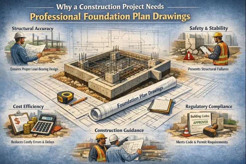
Why a Construction Project Needs Professional Foundation Plan Drawings
It’s all about risk management.
● Permit Compliance
Foundation plans are required to pass permits. And for hassle-free approval, your drawings must meet:
- IBC (International Building Code) and local amendments.
- ASCE 7 for loads.
- ACI (concrete) standards.
- Local municipality requirements and checklist items.
Pro Tip: Along with dimensions, add reasoning, standards referenced, and proper document formatting. This require for seamless project approval.
● Contractor Accuracy
When contractors get a detailed CAD plan, field adjustments drop. You experience less guesswork, fewer RFIs, and fewer costly site fixes. Above all, you can bid accurately because the project scope is clear.
● CAD Accuracy vs. Hand Sketch
A hand sketch is fine for conceptual conversation, and not for permit submission. CAD offers:
- Precise dimensions.
- Layer control.
- Schedules and automated quantities.
- Easy revisions.
● Construction Tolerances & Layout Control
Show acceptable tolerances in your foundation plans: e.g., footing layout tolerance ±25 mm or as dictated by the structural engineer. Also, provide grid control and instructions for batter boards.
● Backfill & Compaction Requirements
Specify compaction lifts and the required percent compaction. e.g., 95% Standard Proctor, and locations where compaction testing is required. This avoids post-construction settlement.
● Temporary Works/Shoring
If deep excavation is needed, show shoring requirements and sequence. Even if your plan doesn’t design shoring, note that shoring drawings will be required and who will provide them.
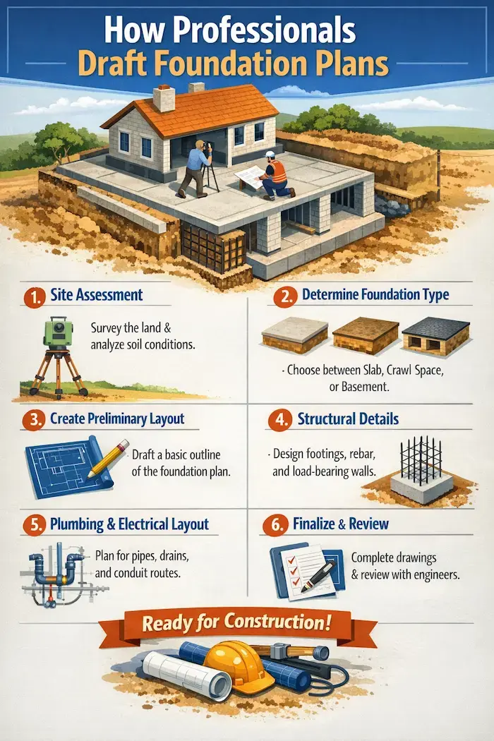
How Professionals Draft Foundation Plans
1. Pre-Drafting: Soil Report & Structural Engineering Review
Drafters start by collecting a site survey, geotechnical report, architectural footprint, and MEP rough-in locations. The soil report answers whether shallow footings are fine or deep foundations are needed.
They review:
- Geotech recommendations.
- Structural load cases.
- Code requirements.
If one skips this, expect financial surprises.
2. Drafting the Initial Foundation Layout
Then, the experts produce the plan view, including footing locations, slab extents, gridlines, and schedule tags. That initial draft goes to the structural engineer for reinforcement and load checks.
3. Finalizing Sections & Foundation Details
Once the engineer signs off, drafters finalize sections by adding details, including footing‑to‑wall, slab edges, drainage details, and waterproofing, and they also add callouts and cross‑references to architectural and MEP drawings as part of the overall construction documentation process outlined in our Guide to Construction Documents.
4. Compliance, Testing & Inspections Coordination
Next, drafters prepare a list of required tests, including:
- Concrete cylinder test
- Rebar verification
- Compaction tests
- Inspector milestones.
This helps plan inspection timelines and avoid unforeseen financial surprises.
5. Deliverables & File Handover
Typical deliverables include:
- Permit-ready PDF set.
- Editable DWG files (layered).
- Optional Revit/BIM exports for coordination.
- As-built/record drawings once construction is complete.
Professionals include a title block, sheet index, and revision history so the set looks professional.
6. Quality Assurance & Revision
QA check is run for clash detection, dimension checks, and cross-references. Suppose you offer unlimited revisions, state that and the turnaround notes. If not, show the revision policy clearly.
Foundation Details Compliance, Testing & QA
Don’t underestimate inspections. They are where plans meet reality.
● Codes & Standards
Reference the applicable codes early:
- IBC for general building requirements.
- ASCE 7 for loads (wind, seismic).
- ACI for concrete mix and testing.
- Local municipal amendments.
● Inspections & Testing
Common tests and when they occur:
- Soil compaction testing before slab or backfill.
- Rebar inspection before concrete pour.
- Concrete cylinder testing during and after pour (28-day strength verification).
- Slump tests to verify consistency.
- Waterproofing inspection before backfill.
Prp Tip: Include an inspection sequence and who calls the inspector to save time.
● Permit Submission Checklist
Include a permit checklist in the set. This must include:
- Soil report.
- Engineered calculations.
- Complete plan set: foundation plan, sections, details.
- Title block and sheet index.
- Energy/insulation notes as required.
- Any municipal forms or application documents.
Foundation Plans Documentation
Make the handover useful by adding the following details.
● Drawing Set Conventions
- The title block includes the project name, client, and revision history.
- The sheet index lists all sheets and the scale.
- Use consistent scales. E.g., plan: 1:100 or 1/8″=1′-0″; details: larger scale.
● Layering & Line Weights
Use a layer standard for structural, architectural, MEP, and annotations. Line weight hierarchy should clearly separate major elements from minor notes.
● File Formats & Handover
Provide:
- DWG (editable).
- PDF permit set (flattened).
- Revit/BIM exports if needed.
- Exported IFC or formats for civil coordination if required.
● Detail Callouts & Cross-Referencing
Each callout on the plan should link to a detail sheet. This reduces the chance of misinterpretation on-site.
Ready to get a quote or upload a site plan for review? Reach out to CAD Drafters today!
The Role of Foundation Plans in Construction & Site Coordination
This is where foundation drawings meet the mess of the site. Therefore, it is essential to address coordination early.
● Site Grading & Surface Drainage
Show how the site will shed water away from the foundation. Indicate swales, slope directions, and final grading tolerances. E.g., slope away 2% for the first 2 m.
● Utility Coordination
Show sleeves and confirm separation distances from foundations by adding sanitary vs. foundation elements. Avoid placing critical mechanical penetrations through structural footings and plan equipment pads or sleeves through slabs.
● Crawlspace Access & Ventilation
If you use a crawlspace:
- Show access hatch dimensions.
- Note ventilation or conditioned crawlspace requirements.
- Also, include moisture control notes.
● Termite/Soil Treatment & Corrosion Protection
If required by local code or soil report, show soil treatment zones and protective measures. Use corrosion-resistant anchors where soils are aggressive.
● Backfill & Compaction Procedures
Specify backfill material and lift thickness, and where compaction testing is required. Similarly, show protection measures for waterproofing during backfill operations.
Frequently Asked Questions
What is a foundation plan, and why do you need one for permits?
A foundation plan is a top-down drawing showing how a structure is supported below grade. Permits require it because it demonstrates code compliance, structural soundness, and construction detail needed by inspectors.
How to read a foundation plan?
- Start with the plan view, covering gridlines, overall dimensions, and footing outlines.
- Then check the schedules for footing/foundation wall sizes, rebar tags and cross-reference detail callouts for sections and connections.
- Read the general notes for materials, geotech reference, and testing
- Last answer those questions “where/what/how”.
What information is required on a permit-ready foundation drawing?
The following information is required on a permit-ready foundation drawing?
- Plan view with dimensions and grid
- Footing sizes and locations
- Foundation wall/schedule
- Reinforcement callouts and rebar schedule
- Anchor/connection details
- Slab and section details
- Moisture-protection/drainage notes
- Clear reference to the geotechnical report
- Any municipality forms.
- Include a sheet index and engineer stamp if required.
How much does a foundation cost?
Costs vary widely by foundation type, site, and region. Typical U.S. ranges:
- Slab ≈ $4–$16/ft²
- Crawl space ≈ $6–$18/ft²
- Basement ≈ $15–$37/ft²
A small house foundation often falls between $7,000 and $30,000, depending on complexity. You can use a local RSMeans or square-foot estimator for accurate, location-specific foundation estimates.
How deep should footings be?
Footing depth is governed by local code and frost line: many jurisdictions mandate minimum shallow footing depths (often 12″ in some warm areas) but require bearing below the frost line where freezing occurs. For cold climates, consider frost-protected shallow foundations (FPSF) or perimeter insulation to avoid deep excavation; always confirm local frost depth and code (or geotech) recommendations.
What are the foundation details and reinforcement requirements?
Foundation details are the section drawings and callouts showing footing/wall/slab geometry, rebar sizes, spacing, cover, lap lengths, and connection hardware. Reinforcement requirements follow the structural engineer’s calculations and standards (ACI/ACI-318); the plan should include tagged rebar schedules and clear cover/lap notes so inspectors can verify placement.
Can you use a slab-on-grade in cold climates?
Yes, but only with proper design: use frost-protected shallow foundations with adequate subgrade preparation and drainage, or deepen footings below the frost line. Additionally, you can avoid frost heave by eliminating moisture sources, insulating the slab edge (FPSF), and following the IRC/region-specific guidance for cold climates.
How long does it take to get permit-ready foundation plans?
Typical small residential timelines: initial CAD layout in 1–3 business days, permit-ready engineered sets in 1–2 weeks, depending on structural engineer availability and site complexity. Complex sites with retaining, deep foundations, and coastal/seismic constraints take longer.
What is the difference between footing, foundation wall, and slab details?
Footings are the widened base that spreads loads to the soil. However, foundation walls transfer vertical loads from the structure to the footings. And slabs bear floor loads and can be structural or non-structural.
Note: Each needs different reinforcement and detailing.
Can you use a hand sketch for permits?
Rarely. Sketches are fine for early-stage discussion, but permit offices require measured, scaled plans and code references. You can save time and money by going straight to CAD for the permit set.
How to choose the right foundation for a construction project?
Play with soil bearing capacity, groundwater level, frost depth, building program, need for habitable basement vs. budget, and local energy code dictates the best option. Furthemore, coordinate early with the geotechnical and structural engineers, consider long-term maintenance and waterproofing costs, and factor in contractor familiarity. Also, evaluate resale implications and insurance costs early.
What to include in the foundation plans set for easy approval?
Here is the checklist:
- Site survey/boundary lines.
- Geotechnical report attached.
- Foundation plan with dimensions.
- Footing & wall schedules.
- Reinforcement details and schedules.
- Moisture protection and drainage details.
- Title block and sheet index.
- Structural engineer stamp (if required).
- Completed permit application & local forms.
Conclusion
Foundations are boring in the best way: when they’re done well, nothing exciting happens. Although it is boring, it’s a goal. A precise, well-coordinated foundation plan eliminates time and financial surprises, keeps budgets under control, and lets the building above behave the way it was designed to.
If you want permitting to be predictable, give your plan the attention it needs. If you want, we’ll draft the foundation set, coordinate with your structural engineer, and hand over a permit-ready set.