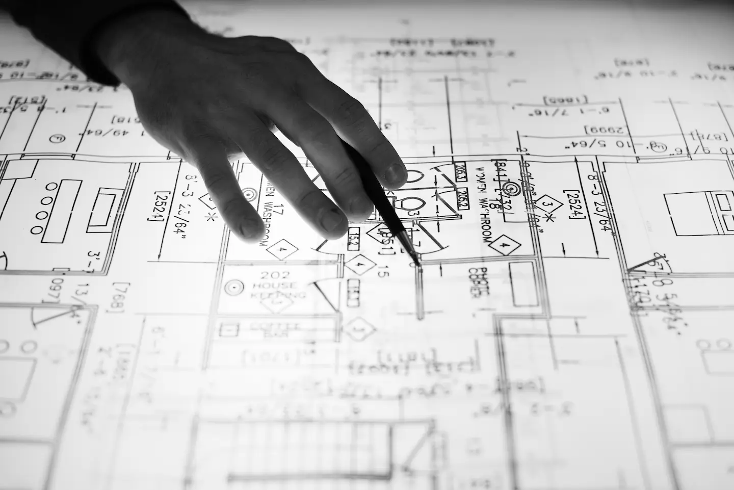
You know that moment when a new drawing set lands in your inbox, and you already feel the headache coming due to some common issues that always show up. Walls don’t line up; dimensions float in space; and notes assume you can read the designer’s mind. All these are communication issues, and not design problems.
In other words, architectural drawings are the language of construction. When they’re clear, coordinated, and intentional, construction projects run smoothly. However, when there are issues with them, they become a headache for a project manager and other teams working on the project.
One must know the details of the architect’s drawings to benefit from them. As a GC or a project owner, you must knwo how they work in the bid room, on site, and during communication calls.
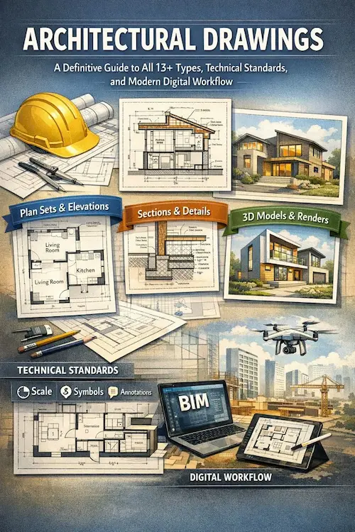
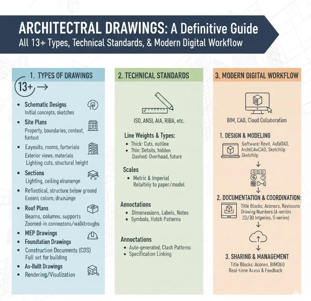
In this guide, we’ll walk through the full lifecycle, the 13+ drawing types you’ll actually use, the standards that prevent confusion, and the modern CAD/BIM workflows that keep teams aligned. Let’s start!
What Are Architectural Drawings
At their core, building architecture drawings are instructions. They translate ideas into a buildable reality. Furthermore, they tell labor teams…
- What to build
- Where to build it
- How big
- How high
- How it connects
- And what it’s made of.
A good set of drawings answers questions before they’re asked. However, a bad set creates RFIs, change orders, and field improvisation.
What Is The Purpose Of Architectural Drawings In Construction?
Architectural drawings…
- Communicate design intent
- Coordinate structure, MEP, and finishes
- Support accurate budgeting and project scheduling
- Helps GCs and subcontractors meet permitting and code requirements
- Reduce guesswork in the field and keep everything realistic
When they are correct, you can go ahead with your construction plans with confidence.
What Makes Architectural Drawings Successful?
After many years of working in the construction field, we have never seen perfect drawings on the first attempt. There is always a need for some modifications when plans proceed. So, perfect drawings are never available, but effective ones play a role in smooth construction. Let’s understand what is meant by Effective Drawings!
Effective drawings are those that…
- A supervisor can clearly understand at first glance. This means the architectural drawing and design must show transparent lineweights, notes, and the meaning of a white space.
- Show consistency throughout the report. They must contain the same symbols, same abbreviations, and same scale logic to avoid confusion and conflicts.
- Effective drawings are professionally buildable. They provide clear details on equencing, access, tolerances, and real‑world constraints.
- They must tell the same story on all pages and lines. There should be no difference between plans, sections, and timeline estimates, even when multiple trades overlap.
- Above all, there should be accurate dates, revision history and responsibilities mentioned in the summaries.
Historical Context & Evolution Of Architectural Drawings
Architecture drawing pans didn’t start with software. They started with charcoal, vellum, and hand‑drawn judgment. For decades, drafting boards ruled. Precision came from experience and discipline.
Then CAD changed everything. With CAD, lines became editable, revisions sped up, and standards became easier to enforce.
And now BIM coordination has pushed the evolution further. Detailed drawings are no longer isolated sheets; they’re outputs from intelligent models that know what a wall is, not just where a line sits.
That shift, from manual work to digital, has changed the whole game. Today, coordination is made earlier, so mistakes appear sooner, and documentation becomes more reliable.
The Architectural Design and Documentation Process
If architect drawings feel confusing, it’s usually because no one explains when each drawing exists, or why. Drawings don’t all show up at once; they evolve, and each phase answers a different question.
Let’s walk through the four core phases the way they actually happen in the real world.
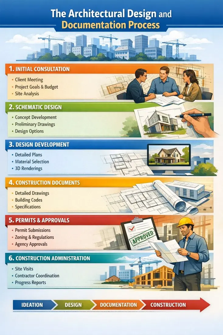
Phase 1: Schematic Design (SD)
This is the exploration phase. Nothing is locked in yet, and that’s the point. At this stage, drawings are loose and conceptual. You’re looking at rough layouts, massing studies, and big-picture relationships. During this stage, you also get “how the building sits on the site”, “how spaces connect”, and “what the scale feels like”.
Simply put, these drawings are asking one simple question: “Does this work?”
In results, you get:
- Conceptual floor plans
- Site diagrams and zoning studies
- Preliminary sections and elevations
- Basic area takeoffs
For contractors and builders, SD drawings aren’t for pricing or construction; however, they’re for understanding intent, including estimating ranges, and identifying early issues before they get expensive.
Phase 2: Design Development (DD)
This is the phase when things get serious. The design is no longer just an idea. In this phase, systems are selected, dimensions tighten, structural grids appear, mechanical zones start to make sense, and coordination begins between architecture, structure, and MEP.
These drawings answer another question: “Can we actually build this?”
In results, you get:
- Dimensioned plans and sections
- Preliminary structural layouts
- Early MEP coordination drawings
- Material selections and assemblies
Accuracy should be highest in this phase since it can save hours and dollars later.
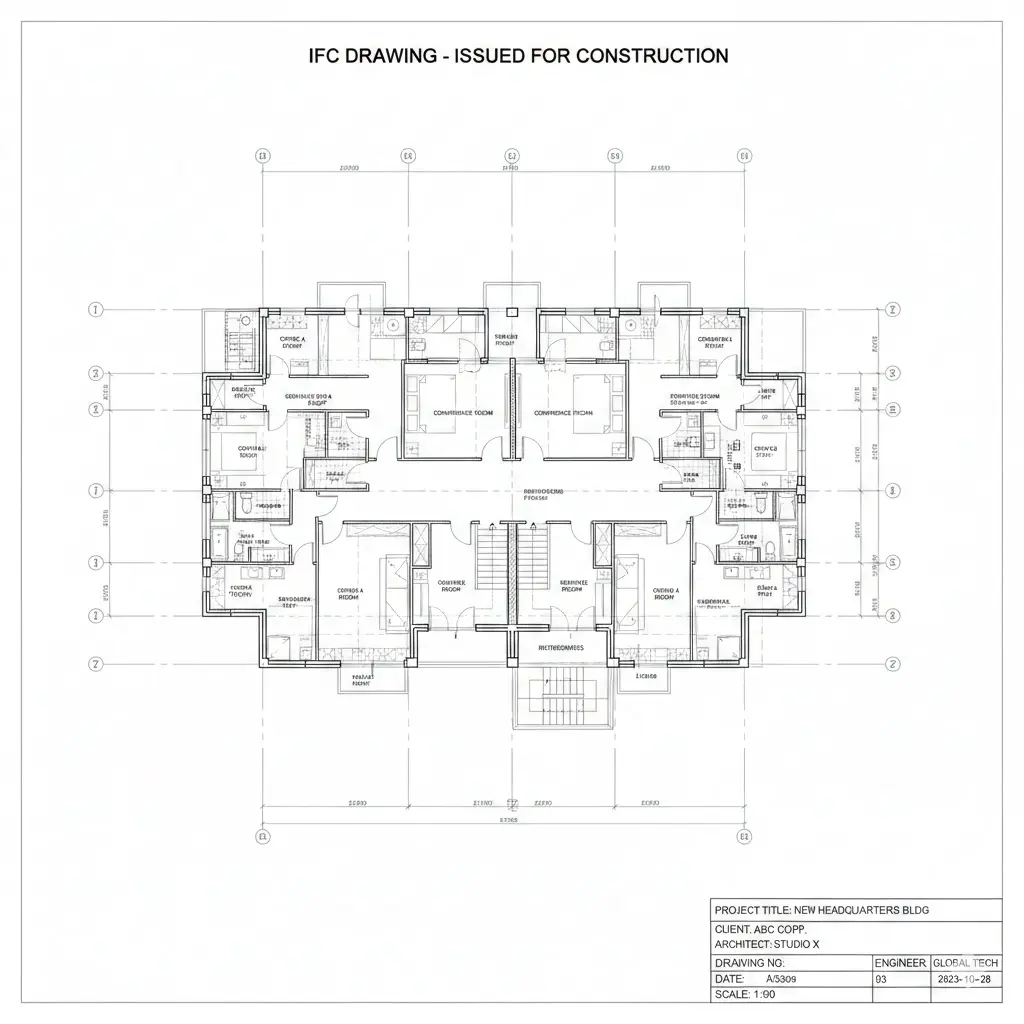
Phase 3: Construction Documents (CD)
This is the contract set where no guesswork is allowed. Construction Documents are the rulebook that translates design into instructions. Everything must be clear, measurable, code-compliant, and coordinated across trades. These drawings are legally binding.
They answer one final question: “Build it exactly like this.”
In results, you get:
- Fully dimensioned plans, sections, and details
- Schedules (doors, windows, finishes)
- Comprehensive architectural details
- Coordinated structural and MEP drawings
Phase 4: Construction & As-Built Drawings
This is the step where reality steps in. Here, field conditions change, and materials shift. Installations don’t always match the plan. As-built drawings document what was actually constructed, not what was originally designed.
These drawings defend owners, contractors, and future renovators because five years from now, when someone asks: “What’s really behind that wall?”, you will put as-builts on the table.
The 13+ Core Types of Architectural Drawings
| # | Drawing Type | Purpose | Typical Scale | Used By |
| 1 | Site Plan | Property, access, utilities | 1:200–1:500 | Civil, GC |
| 2 | Floor Plan | Layout & dimensions | 1:50 / 1:100 | All trades |
| 3 | RCP | Ceilings & lighting | 1:50 | Electrical |
| 4 | Elevations | Exterior faces | 1:50 | Envelope trades |
| 5 | Sections | Vertical relationships | 1:20–1:50 | Structural |
| 6 | Details | Construction clarity | 1:2–1:10 | Installers |
| 7 | Schedules | Doors, windows, finishes | N/A | Purchasing |
| 8 | Structural Drawings | Load‑bearing systems | Varies | Structural |
| 9 | MEP Drawings | Services coordination | Varies | MEP |
| 10 | Roof Plan | Slopes & drainage | 1:100 | Roofing |
| 11 | Landscape Plan | Exterior works | 1:200 | Landscape |
| 12 | Finish Plans | Flooring & materials | 1:50 | Finish trades |
| 13 | As‑Built Drawings | Record condition | Same as CD | Owners |
| 14 | Presentation Drawings | Visual communication | Variable | Clients |
| 15 | Shop Drawings | Fabrication accuracy | Detailed | Fabricators |
Modern projects require specialized plans that go beyond basic floor plans. Below is the table showing specialized plan types along with purpose, scale, and users.
| Plan Type | Purpose | Typical Scale | Used By |
| Interior Elevation | Wall materials, finish heights | 1:20–1:50 | Millwork, finish trades |
| Furniture/FF&E | Furniture layout + power/AV | 1:50 | FF&E installers, interior designers |
| Millwork | Detailed cabinetry & joinery | 1:10–1:20 | Fabricators |
| Lighting/Power | Fixture location, circuits | 1:50 | Electrical contractors |
| Acoustics | Absorption, wall/ceiling types | 1:50 | AV/Acoustical consultants |
| Signage | Wayfinding, mounting details | 1:20 | Sign contractors |
You must include these sheets where they matter. They save time and reduce on‑site change orders.
Explore every architectural drawing type and learn how modern workflows bring them to life read the complete guide.
Building Architectural Drawings: Technical Standards
What is a Title Sheet & Why They Matter
The title sheet is the first thing everyone opens. Therefore, always treat it as the project’s operating manual. Here is what to put on the title sheet.
- Project name, address, and owner
- Key contacts (architect, GC, consultants) with phone/email
- Project number and sheet index (sheet list)
- Drawing revision block and approval block
- Project description and scope summary
- Abbreviations and legend (symbols, line types, hatch patterns)
- General notes that apply to the entire set (materials, tolerances, references)
A clear title sheet saves time. Inspectors, estimators, and subcontractors all look here first for standards and expectations. Missing abbreviations cause guessing, and missing a revision block causes disputes.
What Abbreviations Look Like In Construction Architectural Plans?
| Abbrev | Meaning |
| AFF | Above finished floor |
| CL | Centerline |
| NTS | Not to scale |
| TYP | Typical |
| O.C. | On center |
Guide For General Notes
- Do not scale drawings for dimensions; instead, use written dimensions. Verify all dimensions on site before fabrication.
- All work to conform to local building codes and referenced standards listed on this sheet.
- Contractor to verify existing conditions and report discrepancies to the architect before proceeding.
- All materials and finishes shall be installed per the manufacturer’s recommendations unless noted otherwise.
What Is a Cut Plane / Plan View
A typical architectural floor plan is a horizontal slice taken approximately 4′ (1.2m) above finished floor level. Therefore, doors and windows show as they do in plans. If a plan is a different cut, you must call it out.
Common Scale Conventions (Imperial & Metric)
| Drawing Type | Typical Scale (Imperial) | Typical Scale (Metric) |
| Site Plan | 1″ = 20′ (1:200) | 1:200 |
| Floor Plan | 1/8″ = 1’‑0″ (1:96) or 1/4″ = 1’‑0″ (1:48) | 1:50 / 1:100 |
| Elevations | 1/8″ = 1’‑0″ (1:96) | 1:50 |
| Sections | 1/4″ = 1’‑0″ (1:48) | 1:20 / 1:50 |
| Details | 1″ = 1’‑0″ (1:12) or larger | 1:5 / 1:10 |
Pro tip: Always show a graphic scale bar and the written scale. Don’t assume the reader will interpret a scale mark correctly when printing at different sizes.
What Is Phasing & Why Does It Matter?
Phasing plans show how and when parts of a project are built. It is essential for occupied site work or multi‑stage projects. The following are the elements of the phasing plan:
- Work area boundaries per phase
- Temporary access and egress routes
- Demolition and protection sequences
- Temporary utilities and hoarding
- Schedule overlay (phase vs calendar)
You can also use the checklist below to verify phasing drawings.
- Are existing occupants sheltered from dust, noise, and access loss?
- Is there a clear sequence for building envelope work to maintain weather tightness?
- Where are temporary services routed, and when do they switch over?
Temporary works, including shoring, scaffolding, and hoarding, should be shown or referenced. If a temporary structure affects permanent work, note who is responsible for removal and restoration.
Construction Drawings Vs Permit Sets
It’s tempting to assume the permit set and the construction set are the same because they’re not.
Permit Sets…
- Focus on code compliance, zoning, site metrics, egress, and life safety
- Often, a strip of construction detail and shop drawings
- Submit for approvals; may be publicly viewed
Construction Sets…
- Provide comprehensive details, schedules, fabrication notes, and coordination drawings.
- Include specifications and shop drawings as appendices or references
- They are used for bidding, permitting in some jurisdictions, and building
Best Practice: Prepare a permit set that contains the required code information, and a separate construction set that contains the fine details contractors need. Use the title sheet to flag which set is which and provide a revision log.
What Are Expanded Shop & Fabrication Drawings?
Shop drawings turn design into manufacture. They’re usually produced by the contractor, subcontractor, or fabricator and then reviewed by the architect/engineer. Here are the common shop drawing types and pitfalls.
| Specific Trade | Shop Drawing | Common Pitfalls |
| Curtain Wall | Anchor layout, mullion sections, glazing details | Anchor locations are misaligned with the structure |
| Structural Steel | Connection plates, bolt patterns, camber tables | Insufficient tolerances for on‑site fit |
| Millwork | Elevations, section through casework, fastener schedules | Missing substrate or field‑measured dimensions |
| HVAC | Duct layouts, support systems, diffuser locations | Diffusers clash with the structure or lights |
| Elevator | Shaft layout, pit details, machine room | Clearances are insufficient for maintenance |
| Prefab Elements | Panelized wall/roof shop drawings | Mismatch between factory tolerances and site tolerances |
Pro Tip: Require shop drawings in the contract submittal schedule and set a maximum turnaround time plus a single round of markup and resubmission. This will keep fabrication on time.
What Are Schedules In Architectural Drawings?
Schedules are compact, machine‑readable tables that save pages of repetitive notes. Here are the Important schedules to include:
- Door schedule (type, size, hardware spec)
- Window/glazing schedule (U-value, size, frits)
- Finish schedule (floor, wall, ceiling) with room references
- Lighting & fixture schedules (lumens, mounting, control)
- Equipment schedules (mechanical units, capacities)
- Panel schedules and single‑line diagrams (electrical)
- Wall / Partition type schedule (assemblies and fire ratings)
All About Modernism In Construction Architectural Drawing
Think about a project today: drawings aren’t just lines on paper; however, they live, breathe, and evolve in digital spaces. And the workflow reflects that reality. Instead of emailing PDFs back and forth, teams collaborate in shared environments. Revisions are logged, access is permission-based, and every stakeholder, including architects, contractors, engineers, and subcontractors, works from a single source of truth.
Here’s how modernism is making this happen.
CAD Software
CAD platforms like AutoCAD, DraftSight, and others remain the foundation for most architectural details. They handle:
- Floor plans, elevations, sections, and details
- Layer management and lineweight conventions
- Dimensioning and annotation
- Symbol libraries and reusable blocks
Here is a table showing the comparison between multiple CAD tools so that you can choose the best one.
| Software | Strength | Best Use Case | Output Formats |
| AutoCAD | Precision & industry standard | 2D plans, sections, details | DWG, DXF, PDF |
| DraftSight | Lightweight, cost-effective | Small/medium projects | DWG, DXF, PDF |
| BricsCAD | Affordable, 2D + 3D | Mixed 2D/3D, BIM prep | DWG, PDF |
| Vectorworks | CAD + BIM | Interior and landscape | DWG, PDF, IFC |
BIM Platforms
BIM software, including Revit, ArchiCAD, and others, changes the game. Instead of producing isolated drawings, BIM integrates everything in a single intelligent model:
- Floor plans, elevations, and 3D views link automatically
- Material quantities and schedules are updated in real time
- Clash detection identifies conflicts between MEP, structural, and architectural models before they hit the site
Using this, contractors can pull accurate architectural drawing plans, details, and quantities directly from the BIM model. This reduces RFIs, change orders, and last-minute surprises.
CAD Software Vs BIM Platforms
| Feature | CAD | BIM |
| 2D Plans | Yes | Yes (from model) |
| 3D Views | Limited | Full parametric |
| Quantities & Schedules | Manual | Auto-updated |
| Clash Detection | None | Integrated |
| Collaboration | Limited | Cloud-enabled |
The Role Of AI and Automation In Architectural Drafting
AI isn’t science fiction anymore. Drafting automation tools help:
- Auto-generate floor plan layouts from initial sketches
- Suggest linework corrections, dimension checks, and annotation consistency
- Detect missing references or mismatched symbols
Example
Some platforms can scan a PDF drawing and produce a preliminary CAD version in hours instead of days. Not perfect, but it accelerates initial drafting and frees senior drafters for complex details.
The Role Of Cloud Collaboration and Version Control
Here’s what’s really changed the way architectural drawings are shared:
- Shared platforms: BIM 360, Revit Cloud Worksharing, or AutoCAD Web
- Version history: Each revision logged, with user notes
- Permission controls: Stakeholders see only what they need
- Mobile access: Field teams view drawings on tablets or phones
Instead of emailing PDFs and waiting for feedback, everyone sees live updates. That reduces errors, redundant markups, and outdated print sets.
Quality Control & Review Process
Even in a digital workflow, human oversight matters. Reliable architectural firms implement:
- Peer review: Each sheet is checked by a second drafter for completeness
- Cross-disciplinary check: Architectural, structural, and MEP models compared for clashes
- Automated checks: CAD/BIM tools run scripts to flag missing dimensions, unreferenced layers, or orphaned elements
- Final QA: Verified against project standards, codes, and client requirements
Pro Tip: Build a revision log that shows every change, who approved it, and why.
FAQs
What is the difference between a construction drawing and an as-built drawing?
Construction drawings are the planned set used for building. As-built drawings are updated post-construction to show exactly what was built, including modifications made on-site.
Why are construction shop drawings important?
Shop drawings translate design intent into fabrication instructions for specialized trades like millwork, curtain walls, and HVAC, reducing errors and installation delays.
Can CAD software replace BIM?
Not entirely. CAD handles 2D plans and details efficiently. BIM platforms integrate 3D modeling, coordination, clash detection, and schedules, making collaboration more seamless.
How does modern cloud collaboration improve workflow?
Cloud platforms centralize files, log revisions, provide permission-based access, and allow field teams to view live updates, drastically reducing miscommunication and errors.
What is a key plan in construction architectural drawings?
It is a small diagram that shows the project location in a larger context, especially important for multi-building campuses, phased work, or partial-site plans. You must place it on the title sheet or the first relevant sheet.
What are existing or measured drawings?
Measured drawings work as a baseline for renovations. They document what’s actually there, including structure, utilities, and finishes.
What is the purpose of demolition drawings?
They show what’s removed and in what sequence. Demolition drawings include:
- Extent of demolition (clear hatch)
- Temporary protections and shoring
- Disposal or recycling notes
- Protection for adjacent occupied spaces
What are the trending rendering techniques common among drafters?
- 2D diagrams for construction
- 3D axons for understanding
- Photorealistic renders for communication
How to set title blocks and sheet numbering?
A professional set is predictable. Use this format
Discipline + Sheet Type + Sequence.
Example: A‑101 = Architectural, Floor Plan, Sheet 1.
What is the most important architectural drawing?
Floor plans because every trade touches them.
Last Words
Architectural drawings aren’t just lines on paper or pixels on a screen; they’re the bridge between imagination and reality. When they’re clear, accurate, and coordinated, construction projects move faster, costs drop, and labor knows exactly what to build.
For contractors, detailed architectural drawing plans and schedules reduce RFIs, prevent delays, and give field crews confidence. You get fewer surprises and smoother installs. Similarly, for architects, properly coordinated drawings defend design intent while keeping construction feasible—less compromise, fewer site questions, and stronger control over finishes and details.
At CAD Drafters, we translate design ideas into build-ready architectural drawings and detailed plans that contractors trust and architects can rely on, whether it’s permit sets, construction documentation, or as-built revisions. Accuracy, clarity, and practicality are non-negotiable at our company.
When your next project can’t afford miscommunication, missing details, or late-night fixes, let us help you bridge the gap between design and construction!
Get your precise, build-ready architectural drawings today and keep your project moving smoothly!