Even minor misunderstandings about a model’s details can cause major project delays. For instance, on a recent hospital project, ordering a part from an early LOD100 model nearly doubled the fabrication lead time. Situations like this highlight why BIM’s Level of Development (LOD) is so important.
Each model element’s LOD guides the team on the development and reliability of the information in a particular phase of drafting. In other words, it clarifies whether a wall in the plan is a rough placeholder or a precise, build-ready element. By defining LOD expectation early, all the team members stay aligned, eliminating clashes, coordination issues, and hence the need for rework.
Understand how LOD translates to paper by exploring different types of architectural drawings.
What Does LOD Stand For?
In BIM, LOD stands for Level of Development. It was sometimes called Level of Detail, but industry leaders now emphasize development to highlight model completeness, not just graphics. The AIA clarifies that LOD100 through LOD500 form a framework so all stakeholders understand what the model element represents.
In practice, this means a LOD label answers: How much can we rely on this model element right now? AIA warns that two elements might look identical, but their LOD tells you how much information is actually behind them. In contracts and BIM execution plans, expert teams spell out the particular requirement of LOD with time specifications, so nobody assumes a concept model is shop-ready.
What Is LOD in BIM?
LOD is a standardized language for BIM model maturity. It defines the amount of detail, accuracy, and reliability each element should have at each project phase.
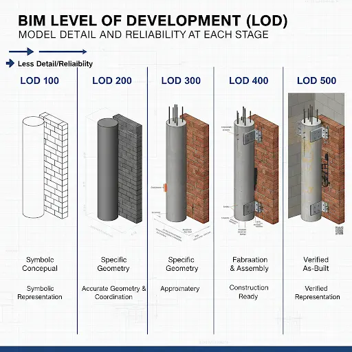
For example, Autodesk explains that at higher LODs, model elements include more specific geometry and data for construction. However, at lower LODs, elements are more symbolic. The American Institute of Architects introduced the five-level LOD system in 2008 (later expanded by industry groups to six levels) to give designers and builders a common framework.
Today, most BIM Execution Plans use an LOD matrix to define exactly which elements must reach which LOD by each milestone. In short, LOD in BIM tells everyone on the team how ready the model is for its intended use, whether that’s schematic design, construction documentation, or fabrication.
See how these standards fit into the overall project lifecycle in our detailed overview of what is BIM.
Deatils On BIM Level of Development (LOD 100–400)
● LOD 100 (Conceptual Design)
At LOD 100, the BIM model is purely conceptual. Professionals show elements as basic masses or symbols, essentially placeholders.
For example, an HVAC system might appear as a single 3D box, or a stair might be a simple ramp volume. The focus is on overall shape and location, and not detail. Quantities and dimensions at this stage are very rough and suitable only for feasibility or high-level budgeting.
Experts often use LOD100 for early site planning or space programming. For example, architects might model the gross floor area or room volumes to check compliance with codes. However, no one should order materials from an LOD100 model.
AIA notes that one must consider the information from LOD100 elements as approximate. In practice, using only LOD100 can lead to costly errors: one firm found that relying on an LOD100 wall width under-estimated masonry takeoff by 25%, causing a budget overrun later. At this stage, you would refine to LOD200 before committing to bids or orders.
● LOD 200 (Schematic Design)
Moving to LOD 200, the team defines elements with approximate geometry and generic components. Walls have real thickness, structural members have defined spans, and mechanical rooms have space zones, but each is still generic.
For example, ductwork may be modeled as simple rectangular tubes placed in the ceiling void, without specifying fittings. The model now includes approximate quantities, sizes, and locations, so initial takeoffs and cost estimates improve.
Autodesk describes LOD200 as refined enough to analyze spatial relationships. In practice, at LOD200, a contractor can more accurately forecast material needs, like linear footage of piping, while still keeping the design flexible. For instance, on an office tower, the team modeled HVAC risers at LOD200 to lay out major shafts; this revealed a conflict between plumbing and electrical that we resolved before detailed design.
However, LOD200 still isn’t construction-ready: if you had ordered ducts from this model, you would soon discover missing fittings and offsets.
One common pitfall is taking LOD200 as final: for example, ordering a custom window at LOD200 led to a wrong frame size, because the model hadn’t yet included curtain wall mullions. Always remember: at LOD200, the information is approximate and should guide decisions, not fabrication.
● LOD 300 (Detailed Design)
At LOD 300, each element in the BIM model matches its real-world geometry and size. This is the stage of design development and construction documentation. Now walls meet at exact angles, beams have real span lengths, and the team runs MEP with accurate offsets.
LOD300 elements include specific systems and assemblies in the correct locations. In practical terms, this means you can extract reliable quantity takeoffs and coordinate trades effectively. For example, a contractor can take the LOD300 model of a slab and get the exact concrete volume and rebar lengths. The team finds LOD300 is where serious clash detection happens: since geometry is accurate, spatial interference can be caught. On one industrial plant, running Navisworks clashes on an LOD300 model showed that a cable tray intersected a duct; fixing that virtually saved a night of rework on site.
Autodesk notes that the teams use LOD300 models for producing construction documents. Indeed, permit drawings and trade drawings typically derive from a LOD300 model. That said, LOD300 still allows some small field changes; think of it as design complete. For example, a final wall type might still be refined later, but dimensions are settled. Designers must ensure the LOD300 model matches the approved construction drawings exactly.
● LOD 350 (Coordination Level)
LOD 350 builds on LOD300 by adding connections and interfaces between elements. Team name it as the coordination level. At LOD350, the model doesn’t just have precise geometry; it also shows how systems tie together. Examples include light fixtures with supports, plumbing fixtures with exact valves and fittings, or structural frames with connection plates.
The Autodesk framework highlights that experts use LOD350 to generate construction documents and even shop drawings. In practice, a LOD350 model has enough detail to check multidisciplinary fit. For instance, an electrical conduit run will include junction boxes at the correct heights, intersecting properly with structural beams or ceilings. This level often involves multiple teams: MEP modelers ensure ducts and pipes connect to equipment and walls, while structural engineers model beam splice plates or embed plates.
Example: before finalizing the electrical design, the team updated the model to LOD350 and discovered an outlet offset error that would have conflicted with a column. Fixing it in the model avoided tearing out new conduit in the field. LOD350 doesn’t usually include every bolt or weld, but it does include enough detail that if something still doesn’t fit, it will show up now, not later.
● LOD 400 (Fabrication & Assembly)
LOD 400 is a shop model. At this stage, the BIM elements have the full fabrication-level detail. That means the teams mold all parts with their connections, assemblies, and installation information.
For example, a structural steel beam at LOD400 will include splice plates, bolt holes, and field welding information. A piece of HVAC duct will have every elbow and end cap modeled. Non-graphic data, like material specs or flange types, is also populated.
Autodesk describes LOD400 as fabrication and assembly, meaning the team details the models enough to go straight to manufacturing. In real projects, experts use LOD400 when producing shop drawings or ordering custom components. For instance, a precast concrete facade panel at LOD400 would include rebar layout and lifting points. However, because creating LOD400 is time-intensive, teams follow it only when needed.
Team typically reserve LOD400 for long-lead or critical path elements. For example, on a high-rise, the steel fabricator took the LOD400 model and directly exported it to CAM software to cut plates. On a hospital job, the plumbing subcontractor used the LOD400 model to prefabricate riser modules off-site. It’s worth noting that at LOD400, nearly everything is decided; changes after this point become very costly.
Learn how high-level modeling improves accuracy in our guide on design drawings vs. shop drawings.
Why Choosing the Right LOD Is Important for Your Project
Picking the proper LOD for each phase is like setting the thermostat in a climate: too high or too low can be inefficient or risky. Here is why choosing the right LOD is essential.
● Clear Project Notes
A precise LOD plan ensures every team understands what they should model and expect. If you use a model too early, you risk overtrusting it; if you over-model too soon, you waste effort. For example, if a contractor assumes a wall is fully defined at LOD200, they might order precut panels prematurely.
● Reduced Risk
AIA warns that LOD tells you how developed the information is and how much it can be relied upon. So choosing the right LOD minimizes risk.
● Avoid Costly Rework
In construction, this translates to avoiding costly rework. TrueCADD notes that a higher LOD enables more accurate takeoffs and tighter budgets. In other words, when a team appropriately matches LOD to the task, cost estimates, schedules, and material orders become much more reliable. For instance, delivering wall quantities from a LOD300 model, instead of LOD100, can cut re-estimation work in half, since the wall geometry is confirmed.
● Better Communication
Proper LOD selection also improves communication. It creates a shared language so the owner, designers, and builders don’t talk past each other. As one BIM manager said, “When LOD is written into the contract and checked, everyone knows exactly what to expect at each submittal.” In summary, aligning LOD with project milestones builds trust among teams, reduces confusion, and focuses effort where it’s most needed, ultimately protecting both schedule and budget.
Accurate LOD selection is vital for precise estimates; learn more in our guide on what is a takeoff in construction.
Common Mistakes To Avoid When Defining LOD in BIM Projects
Even experienced teams can get confused about LOD.
● Undefined LOD
A top error is leaving LOD undefined or confusing. Saying “we’ll deliver LOD300” without clarifying what that includes can lead to misunderstandings.
● Over&Under Modeling
Another trap is over-modeling. This means adding excessive detail well beyond the project’s needs. TrueCADD highlights that over-modeling increases complexity and cost. For example, modeling every tile or screw in LOD300 is wasted effort.
Conversely, under-modeling happens when expected details are ignored. An example is modeling a wall with no thickness or studs at LOD300. This often forces extra work later.
● Miscommunication
Miscommunication is another common issue. Different disciplines might use LOD numbers differently. In one case, an architect and MEP firm both thought LOD350 without a meeting, and ended up with inconsistent definitions, which meant the coordination meeting got derailed, clarifying what had been delivered.
● Ignoring the LOD vs. Level of Detail distinction
Many projects also ignore the LOD vs. Level of Detail distinction. Teams sometimes ask for more detail without specifying what that means for reliability. That’s why the best practice is to create a project-specific LOD matrix in the BIM Execution Plan. This matrix lists each element or system and the required LOD at each phase, leaving no guesswork.
● Skipping Reviews & Not Updating LOD Documentation
Additional mistakes include skipping reviews and not updating LOD documentation when scope changes. According to industry experts, failing to verify that models meet their target regularly LOD is a costly oversight. The solution is clear communication. You should set LOD expectations upfront, review them at each milestone, and document everything. This ensures the team isn’t surprised by model shortcomings when it counts.
Avoid costly errors by ensuring your team follows a formal guide to construction documents for better clarity.
How Do Professional BIM & CAD Experts Ensure Accurate LOD?
By integrating some practices, professional BIM/CAD teams ensure the model’s development matches the project plan. Clear communication, documented standards, and diligent QA make LOD management systematic rather than guesswork. In experts’ experience, projects that follow the following steps easily pass through design reviews.
Experienced BIM managers follow a rigorous workflow to hit the right LOD. Below are the details on their process.
1. Document LOD Requirements
First, they document LOD requirements upfront. The project’s BIM Execution Plan (BEP) or contract should include a detailed LOD matrix. This spells out which elements, including walls, slabs, equipment, etc., must reach each LOD and who’s responsible.
Therefore, all professionals start every project with an initial meeting. They review the LOD matrix line by line, asking, for instance, “What geometry do the team expect for plumbing fixtures at the DD (design development) stage?” Getting alignment early avoids confusion in the scope of work.
2. Use Of Industry Standards & Checks
Second, they use industry standards and checks. They reference AIA’s digital practice guidelines and ISO 19650 when defining LOD so the team speaks the same language as engineers and contractors.
Throughout modeling, experts run internal QA. Senior modelers review all elements against the target LOD. For example, if a model should be LOD300, they verify that doors have correct dimensions and materials. If it’s LOD400, they check that steel members include all splice plates and that rebar is fully modeled.
Furthermore, they often use clash detection (Navisworks or Solibri) not only to find interferences, but also to verify LOD. For instance, a clash report might reveal a gap where a connector was missing, signalling the model isn’t fully detailed.
3. Leverage Technology & Checklists
Third, the teams leverage technology and checklists. In Revit, they set up project templates and view filters that highlight element status. They maintain a checklist of LOD criteria (geometry, attributes, documentation) for each discipline. Moreover, they use cloud platforms, like BIM 360 and ProjectWise, to keep everyone on the latest model. This avoids working off old LOD versions.
Regular coordination sessions also help. Professionals present the latest model to all trades at each phase, and walk through key elements to confirm this is LODX. If any gap appears, the team updates the model accordingly.
Ensure your project accuracy by exploring our guide on construction as-built drawings.
Commonly Asked Questions
1. How do BIM software tools like Revit handle or indicate different LOD levels?
BIM tools like Revit don’t have a magic LOD switch; it’s managed by modeling practices. Revit users must adhere to standards: modeling elements with the appropriate amount of detail and information for the required LOD. The software has View Detail Level settings (coarse/medium/fine), but those just control graphical detail in views, not the formal LOD definition.
2. Who determines the LOD level needed for each element or deliverable in a BIM project?
LOD levels are typically determined collaboratively at the project’s start. The owner’s requirements (or contract standards) might set overall targets, but the project team, often during BIM Execution Plan development, agrees on who will model what to which LOD. A BIM manager or coordinator will facilitate input from architects, engineers, and contractors to align LOD with each project milestone and use-case. Ultimately, it’s a team decision documented in writing so everyone understands the expected level of detail for each deliverable.
3. Do I need to include disclaimers about LOD when sharing BIM models with other stakeholders?
It’s a good practice to include an LOD disclaimer. Clearly note the intended LOD of the model and what it should (or shouldn’t) be used for. This manages expectations and liability by making sure recipients know the model’s limitations. In short, yes, a brief note about the model’s LOD and allowable uses can prevent miscommunication and misuse of the BIM data by others.
4. What is LOD 500 (as-built), and is it commonly used in BIM projects?
LOD 500 represents an as-built model. At this level, the model element isn’t just design intent; it reflects the actual installed component, verified in the field, with exact size, location, and all data matching the real-world building. LOD 500 models are valuable for facility management since they contain the true final details of the project.
5. What is the Level of Information Need (LOIN) in ISO 19650, and how does it relate to LOD?
ISO 19650 introduces Level of Information Need (LOIN) as a way to precisely define what information is required for an element at a given stage, without over-specifying. It’s essentially a refined approach that moves beyond broad LOD labels. LOIN considers the purpose of the information, the level of detail in geometry, alphanumeric data, and documentation needed for that purpose.
Conclusion
In modern construction, clarity is king. Defining the BIM Level of Development properly is all about clarity. This means knowing exactly how far each model element should be developed at any point. By choosing the right LOD, from 100–400, for each project stage, teams set realistic expectations and avoid costly missteps.
Lower LODs (100, 200) let you explore concepts and budgets quickly, while higher LODs (300, 350, 400) provide the precision needed for coordination, permits, and fabrication. The key is to align LOD with the project’s decision points and deliverables.
The AIA’s LOD framework and best practices (like an LOD matrix in the BIM plan) give us that alignment. In the field, it has been seen how projects stay on schedule and on budget when BIM models are properly dealt with. In other words, contractors get exactly what they need when they need it.
At CDA Drafters, we apply these lessons on every project to ensure that, whether you’re a general contractor, developer, or architect, your team and our team always work from the same playbook. With the right LOD roadmap, your BIM process becomes a powerful tool for efficiency and risk reduction. Let’s start together!