If you’ve ever stood in a mechanical room with a superintendent staring at a misaligned flange, you already know why this topic matters. The steel is in the air, the lift is scheduled, the pressure test window is booked, and someone just realized the simple piping run doesn’t actually fit the way the drawing implied. That kind of mismatch doesn’t just cost labor; it creates schedule conflicts across trades, triggers change discussions, and burns contingency that most projects don’t have to spare.
This is exactly where the pipe spool approach earns its keep. A pipe spool is a prefabricated portion of a piping system assembled in a controlled shop environment and then shipped to the jobsite for installation, built between planned field connection points. The Pipe Fabrication Institute (PFI), an established U.S. pipe fabrication trade association, describes prefabricated spools as pre‑arranged piping components joined between designated field connections, emphasizing that detailing must happen before fabrication begins.
Let’s explore more about pipe spools!
Components of a Spool of Pipe
A spool of pipe isn’t one thing; it’s a managed assembly. The exact contents vary by industry process, power, water, and building services, but the same building blocks show up repeatedly. Understanding these components matters because every one of them has tolerances, orientation rules, and documentation needs that affect whether the spool bolts up cleanly or becomes a field modification.
● Pipe, Wall Thickness, and Project Schedules
The pipe itself is usually defined by nominal pipe size (NPS), wall thickness, often via schedule, material grade, and end prep. In the U.S., common dimensional standardization for welded and seamless wrought steel pipe is covered in ASME B36.10M. This standardizes dimensions for typical piping/pipeline products used across temperature and pressure ranges.
Material specification depends on the service. For example, ASTM A106/A106M covers seamless carbon steel pipe for high-temperature service. It states that the pipe is suitable for bending, flanging, similar forming operations, and welding, also tying nominal wall thickness back to ASME B36.10M.
From a field-practical viewpoint, the schedule and end preparation considerations are essential. A spool that’s dimensioned to centerline but fabricated with the wrong end prep or wrong wall assumption can throw off fit-up, weld profile, and even NDE acceptance expectations, especially on tighter pipe racks or skid packages.
Accurate pipe dimensions and wall thickness coordination rely heavily on proper drafting standards, which we explain in detail in our article on What Is Architectural Drafting.
● Fittings, Reducers, Elbows, & Branch Connections
Most spools include fittings such as elbows, tees, reducers, caps, and speciality outlets (o-lets). Standardization matters here, too. ASME B16.9 covers dimensions, tolerances, ratings, testing, and markings for factory-made wrought buttwelding fittings across a wide size range.
In practical terms, consistent fitting geometry is what makes spool dimensions predictable. When the model assumes one elbow type, say, long radius, but procurement substitutes another without a controlled equal/approved substitution process, the spool can lose critical inches that the field cannot find without rework.
Precise modeling of elbows, reducers, and branch connections follows the same technical logic used in detailed Section Drawings to ensure dimensional clarity and constructability.
● Flanges, Bolting, Gaskets, & Orientation Realities
Flanges are where the field usually discovers drawing weaknesses. Even when dimensions are correct, orientation can be wrong, including bolt holes rotated, flange faces flipped, or a mating flange class mismatched.
ASME B16.5 covers pressure-temperature ratings, materials, dimensions, tolerances, marking, testing, and other requirements for pipe flanges and flanged fittings within its scope.
In the real world, this means flange data is never just a symbol; it’s class, facing type, drilling pattern alignment, gasket requirements, and bolting that must be compatible with the mating equipment nozzle or field flange. If your spool drawing doesn’t communicate bolt-hole orientation where required, the shop may fabricate perfectly to the drawing and still deliver something that can’t be installed without rotating or cutting.
● Valves, Specialty Items, & Where Spools Often Stop
Many spools include valves (gate, globe, check, ball), strainers, inline instruments (depending on scope), and specialty items like expansion joints. Whether these are included in the spool is usually a decision based on weight, protection in shipping, and commissioning requirements.
A disciplined approach is to break the system at logical field make-up points, often at flanges or planned field welds, so commissioning and QA can happen without tearing apart factory work.
● Supports, Shoes, Guides, & Attachments
Some projects include pipe shoes, trunnions, lugs, dummy legs, or support steel welded to the spool. This is where coordination becomes critical, such as when the spool is no longer just piping; it becomes a piece of the structural/support system, and its fit depends on embedded plates, steel elevations, and anchor locations being right.
This is also where laser scanning and model-based verification can help with retrofit work. Laser scanning has been used on piping projects to improve modeling accuracy and reduce field measuring time, with documented cases noting “weeks of labor” saved in field measurement effort when accurate scan data is available.
● The Spool Drawing Container
PFI’s drafting practices standard makes a point most field teams instinctively know: spools must be detailed before the shop can fabricate, and the purpose of shop engineering/drafting is to standardize what’s communicated to the shop floor and minimize misunderstanding.
PFI also notes that spool drawing formats typically include space for material description, labor operations, and even references to code/customer specification, welding procedure, NDE, hydrostatic test requirements, surface prep, weight, and shipping prep.
That’s the difference between a spool that moves through the shop predictably and a spool that sits in waiting on clarification while the jobsite clock keeps ticking.
For a deeper understanding of how technical details are organized and standardized in project documentation, read our guide on Construction Documents.
The Pipe Spool Fabrication Process
Pipe spool fabrication looks linear on paper, but in real production, it’s a controlled loop. The strongest shops treat the drawing package as a controlled manufacturing document.
1. Start with the Governing Code & Project Piping Specification
Before you cut anything, you need to know which code governs the system and what the project specifications require. In U.S. work, that’s often driven by system type:
- ASME B31.3 covers process piping and explicitly includes requirements spanning materials/components, design, fabrication, assembly/erection, examination, inspection, and testing (and it also includes piping that interconnects stages within packaged equipment assemblies).
- ASME B31.1 is commonly used for power piping applications.
- For building-related systems, other B31 sections and local building/plumbing codes may apply depending on the service and jurisdiction; the owner/design authority must determine which code section is most applicable.
A key grown-up reminder from an engineering standards guide used at Los Alamos National Laboratory: guidance documents are not stand-alone, and safe operation depends on competent application of codes/standards; the code largely addresses structural integrity, while the designer must address functional design and other considerations.
2. Create an Engineering, Modeling, & Spooling Strategy
A workable spool break plan accounts for:
- Transport limits (length/weight) and how the spool will be picked and set
- Installation sequence (what must go in first in congested areas)
- Where field welds are acceptable and accessible
- Tie-ins that must remain adjustable until field verification is complete
- Support locations and required clearances
Modern design software reflects this concept directly. For example, piping systems can be divided into spools as prefabricated units, and the spool drawing represents that unit.
In Autodesk Plant 3D, documentation describes a spool drawing as a subset of piping, isometric with start & end points indicating the fabricated subassembly.
3. Spool Detailing & Issuance for Fabrication
PFI recommends spool drawings be in practical, easy-to-handle formats and drawn as arrangement drawings or isometric projections, with proportionate dimensioning between components.
On the tech side, isometrics/spool applications can include dimensions, coordinates, part numbers, cut numbers, tags/labels, and material summaries. In short, they conclude exactly what the shop needs for buildability and traceability.
Before issuing IFC/IFAF (which are issued for construction and fabrication, respectively), treat the spool sheets like you would rebar shop drawings. Going in depth, you can take it as
- Confirming that the embed/equipment/nozzle data is locked
- Support elevations are controlling points
- And validating that the latest model revisions have been captured.
That single discipline eliminates the chances for the most expensive failure mode in spooling: building to the wrong revision.
4. Material Takeoff, Procurement, & Traceability
After the spool drawings are approved/issued, material control begins. PFI’s standard even recommends consistent listing sequences for materials, like pipe, fittings, flanges, branch connections/couplings, miscellaneous, and end protectors. This assists material control.
In real life, procurement risk is often schedule risk. If your bill of materials (BOM) for a spool package is inaccurate, you don’t just order more. You lose your shop slot, you lose planned weld sequencing, and you potentially miss hydrotest/turnover milestones.
5. Shop Fabrication: Cutting, Fit-up, Welding, & Dimensional Control
Most shops run a predictable set of work steps:
- Cutting and end preparation: Cut lengths per the cut list; bevels as specified.
- Fit-up and tack: Assemble with jigs/fixtures where possible; confirm orientation points.
- Welding: Run qualified procedures; record weld IDs per drawing/weld map.
- Dimensional verification: Confirm face-to-face, centerline offsets, and equipment interface points.
- Finish Work: Attach supports/shoes if included; prep for coating/paint if required; protect flange faces for shipping.
Where weld quality is code-governed, the qualification framework matters. Section IX of the ASME Boiler and Pressure Vessel Code is widely used as the welding qualification standard referenced by construction codes; training/technical overviews describe it as covering the welding qualifications’ scope/implementation for code fabrication programs.
6. NDE & Inspection
Projects often require NDE methods based on service category and specific requirements. ASME BPVC Section V contains requirements and methods for nondestructive examination, including personnel qualification expectations and intent to detect surface/internal discontinuities in welds and components.
In the real world, a spool that looks fine can still fail NDE due to fit-up issues, root conditions, or welding variable drift. Proper spool drawings support inspection by clearly identifying weld numbers, weld types, and any special NDE notes. This reduces the chance that the shop misses required examinations.
7. Testing Approach & Safety Reality
Leak/pressure testing requirements typically apply at the system level, but sometimes spools are pressure tested in subassemblies, depending on specifications and logistics. Hydrostatic tests are generally considered safer than pneumatic tests due to the stored energy hazards associated with compressed gas.
A National Board presentation on pressure testing emphasizes that hazards are associated with the sudden release of stored energy, and failures in pressure boundaries can create a significant hazard.
In practice, your fabrication plan should define what is shop-tested vs. field-tested, how vents/drains will be handled, how test blinds will be installed, and what documentation (gauges, calibration, hold times, sign-offs) must move with the package.
Accurate BOM preparation follows the same principles outlined in our guide on What Is a Takeoff in Construction, where material quantification directly impacts scheduling and cost control.
8. Shipping, Receiving, & Field Installation
A spool only creates value if it arrives intact and is installed correctly. That means:
- End protection (especially flange faces)
- Match-marking and labeling that corresponds to the erection drawings
- Planned rigging points where needed
- Receiving inspection on site (confirm spools match the latest IFC)
Then the field work usually becomes:
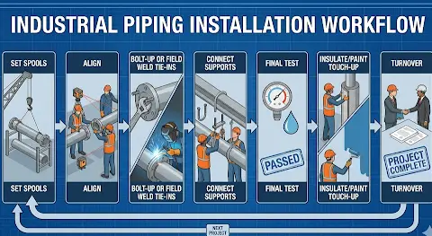
Why Precision Drafting is the Backbone of Fabrication
Most spool failures start upstream in unclear, incomplete, or inconsistent drawings. PFI is blunt about the underlying logic, meaning the bulk of shop work consists of prefabricated spools, and before fabrication begins, the spool must be detailed; the prime purpose is to standardize information to the shop floor, minimize misunderstandings/errors, and help resolve conflicts within contract documents.
Furthermore, it matches what every superintendent has seen: fabrication rework is often just the shop making assumptions because the drawing left gaps.
What a Fabrication-Ready Spool Drawing Communicates
Proper spool drawings act like manufacturing work instructions. Modern spooling/isometric tools describe the inclusion of dimensions, part numbers, cut numbers, tags/labels, and material lists/summaries as part of the spool drawing output.
PFI’s drafting practices also anticipate that the spool drawing format includes space for material descriptions and operational/QA requirements, like welding procedure, NDE, hydrostatic test notes, surface prep, and shipping preparation. All this is a direct acknowledgement that spools are production-controlled assemblies.
For successful results, the drawing must clearly show:
- Field connection points: Which ends are field welds vs. flanged make-ups
- Orientation control: Northing references, equipment nozzle clocking, bolt-hole orientation if required
- Weld identification: Weld numbers tied to weld maps and NDE requirements
- BOM accuracy: Correct specification breaks, correct quantities, correct end preps
- Dimensional datums: What dimension is controlling as per face-to-face, centerline offsets, BOP/TOP elevations
- Fit allowance strategy: Where a field fit allowance is permitted and how it’s documented (PFI even includes abbreviations such as Field Fit Allowance and Field Weld in shop contexts).
Fabrication Drafting Tips
In U.S. projects, spool drawings often sit at the intersection of BIM coordination and fabrication. This is where a disciplined drafting workflow helps:
- Start with coordinated models (or at least coordinated backgrounds) so the piping routing isn’t fighting structure or electrical. Autodesk training describes using Navisworks for 3D coordination to identify and resolve clashes/constructability issues early, reducing rework and project costs.
- Extract spool isometrics consistently. Therefore, it is helpful to plant 3D documentation notes that iso styles determine whether output is an iso or spool drawing, and that spool drawings are subsets of piping isometrics with defined subassembly limits.
- Also, use automatic annotation where possible for change management. Cadmatic documentation recommends creating isometrics at the end of the project and using automatic annotation so changes update correctly.
A Spool Drawing Quality Control (QC) Checklist
Below is a practical checklist you can use when reviewing spools before they go to fabrication.
- Confirm the drawing is the current revision and clouded/revised correctly; superseded spools must be pulled from production queues.
- Verify line number, service, specifications, and design conditions references match the piping particular package.
- Check flange class/facing, and confirm any critical orientation requirements are called out, especially at equipment nozzles.
- Validate centerline dimensions against model control points; watch for tolerance stack-ups across multiple fittings.
- Confirm weld numbering is complete and aligns with any NDE matrix/requirements.
- Confirm that supports/shoes are included only if their field interface points are verified.
- Confirm BOM quantities and end preparations match the drawing (BE/PE, threaded/socket weld, etc.). PFI highlights the importance of consistent material listing practices and clear material descriptions.
Benefits of Using Pipe Spools
When planned correctly, spools don’t just save time; they increase predictability, which is the most valuable commodity on a tight construction schedule.
● Schedule Reliability
The biggest advantage is parallelization. This means that the shop can fabricate while the site is still doing foundations, steel, equipment setting, or overhead rough-in. That removes piping from the critical path when execution is managed well.
● Quality Control
Welding and inspection are more controllable in a fabrication shop than in the field (weather exposure, access limits, congestion). That aligns with why codes put so much focus on qualification, NDE, and inspection documentation, because weld integrity isn’t optional.
Having NDE frameworks like ASME BPVC Section V defined for examination methods and personnel qualification helps standardize how discontinuities are detected and documented.
● Safer & Less Congested Site Work
Reducing field weld volume and field fit-up time reduces congested hot work areas, minimizes time on lifts/scaffolds, and shortens exposure windows where multiple trades fight for the same space.
Even pressure testing risk supports this logic. This means that the stored energy hazards are a core concern in pressure testing safety discussions, especially when compressed gas is involved.
● Better Coordination with BIM & As-built Verification
On renovation and brownfield work, the unknowns are real. Laser scanning has been used successfully to improve modeling accuracy and reduce field measuring time in piping projects. This helps teams route piping and verify clearances against point clouds.
When a project uses scanning with coordinated modeling and disciplined spooling, you reduce the chance that your perfect spool arrives at a site that no longer matches the drawings.
● Transparent Turnover Packages
Spooling also supports documentation. This means that the teams can tie spool IDs to weld maps, NDE reports, material traceability packages, and inspection sign-offs. That becomes valuable at commissioning and later maintenance, especially in regulated or high-liability facilities.
Clear weld mapping and inspection documentation follow the same structured detailing logic discussed in our article on Design Drawings vs Shop Drawings.
Pipe Spool Common Challenges with Solutions
Spools simply shift risk earlier into engineering, drafting, and document control. The teams that struggle with spooling usually struggle because they try to fabricate before the design is ready. Here are some common challenges you can face:
● Design Changes After Fabrication Begins
This is the number one failure mode. If the owner changes equipment, if structural steel shifts, or if clash coordination reveals a conflict after spools are already welded, you are now paying to take back high-quality work.
How to avoid it:
- Define a clear fabrication release gate (model freeze or at least an area freeze).
- Use automatic annotation/update workflows where possible, so late changes don’t create mismatched labeling.
- Treat spool drawings like controlled submittals, and not informal shop sketches.
● Flange Orientation & Rotating Assumptions
On paper, rotating a spool seems easy. In the field, it often isn’t, as the supports, valve operator orientation, drain/vent slopes, and access clearances make rotation impossible. Teams use standards, like ASME B16.5, to govern flange requirements and compatibility. Doing so ensures that the drawing captures the right flange data and any required orientation.
How to avoid it:
- Call out orientation requirements explicitly where the field cannot figure it out.
- Use consistent datums, like north arrows, equipment centerlines, and BOP/TOP references.
- Require a pre-fab check against equipment nozzle orientation drawings when the interface is critical.
● Tolerance Stack-Ups & Close Fabrication
Even if each component is within tolerance, a series of small variances can accumulate. This shows up on long spool runs with multiple fittings where the last flange or field weld doesn’t land where expected.
How to avoid it:
- Dimension from consistent datums, and not floating dimensions.
- Require shop dimensional checks at key hold points before final weld-out.
- Avoid over-spooling. Sometimes, two smaller spools with a planned field weld is the safest approach.
● Material Substitutions & Specifications Breaks
Substitutions happen due to lead time, availability, or purchasing errors. But substitutions without engineering approval are where leaks, rework, and compliance problems start.
How to avoid it:
- Lock BOM to the piping class/specifications. Also, require documented substitution approvals.
- Use clear standard references for fittings and flanges so procurement knows what’s acceptable (e.g., ASME B16.9 for buttwelding fitting dimensional/tolerance expectations; ASME B16.5 for typical flange requirements).
● NDE/Test Scope Confusion
If the drawings don’t clearly state what welds require what examination, and what the acceptance/hold points are, shops either over-test or under-test. Both conditions lead to cost or schedule hit and quality and compliance hit, respectively.
How to avoid it:
- Tie weld numbers to NDE requirements and reference the governing framework.
- Remember that examination method expectations commonly reference standards like ASME BPVC Section V for nondestructive examination methods and qualification structures.
● Shipping Damage & Uncontrolled Site Handling
Poor packaging and careless unloading can damage the spools. That hits hardest on flange faces and valve operators.
How to avoid it:
- Require flange face protection and end caps.
- Provide handling notes on spool sheets (pick points, do-not-lift areas) where needed.
- Perform a receiving inspection at the jobsite before the crane is standing by.
Share your latest model, markups, and specifications; our team will turn them into fast, buildable sheets shortly
Commonly Asked Questions
What should I include in an RFQ when pricing pipe spool fabrication?
Include:
- Latest spool drawing set
- The governing code/spec references
- Required NDE matrix
- Coating/paint requirements
- Aclear scope statement on whether valves/instruments/supports.
If you expect the shop to follow specific drafting conventions for weld numbering, item bubbles, etc., state that up front. PFI drafting practices highlight how spool documents often carry welding/NDE/hydrotest and shipping prep information, so your RFQ should align with that level of clarity.
Are pipe spools only for industrial/process plants?
No. Spooling is used anywhere prefabrication improves control, including industrial units, power, water/wastewater, and even complex commercial work, like central plants, data centers, and hospitals.
How do teams decide where the field welds should be?
Field weld locations are usually chosen based on access, safety, installation sequence, and the need for adjustable tie-ins, especially in retrofit areas where existing conditions can deviate. Tooling guidance for spool drawings commonly recognizes field weld handling and make-up length considerations as part of spool configuration options.
What’s the difference between a piping isometric and a spool drawing?
An isometric usually communicates the full line routing and information for installation; a spool drawing breaks that information into prefabricated subassemblies meant to be built in the shop. Autodesk’s Plant 3D documentation describes a spool drawing as a subset of a piping isometric with defined start and end points indicating the fabricated subassembly.
Do spool drawings need to show inspection and testing requirements?
If you want predictable quality, yes. PFI drafting practices anticipate spool documents carrying references to welding procedure, NDE, hydrostatic test requirements, and related notes. And standards, like ASME BPVC Section V, define nondestructive examination methods/requirements that are commonly referenced by code-driven fabrication programs.
How can I reduce risk on renovation or brownfield spooling where dimensions are uncertain?
Use field verification and, where justified, laser scanning/point cloud workflows before final spools are released. Real project documentation shows laser scanning improving modeling accuracy and significantly reducing field measuring effort, exactly the kind of risk reduction spooling depends on in retrofit spaces.
Conclusion
Spooling is one of the most effective ways to reduce piping risk. It only works when the engineering, drafting, and fabrication package is treated like a manufacturing deliverable, and not a sketch. Industry standards reinforce this mindset as PFI’s drafting practices emphasize that spools must be detailed before fabrication and that the purpose of the drawing is to standardize shop communication and minimize error.
Simply put, the best pipefitters in the world cannot install a spool that was never clearly defined. When the drawing locks down connection points, dimensions, weld IDs, QA requirements, and orientation controls, the shop can fabricate confidently, and the field can install without issues.
That’s why the pipe spool approach works when paired with accurate drafting, disciplined revision control, and code-aware fabrication planning. In simple words, this has remained a backbone strategy for schedule certainty and quality on complex builds.
If your team is preparing for fabrication and needs clean, fabrication-ready spool sheets (isometrics, weld maps, BOM/MTO support, and coordinated revisions), CAD Drafters can support with drafting that reduces site-level guesswork.