
According to the U.S. Census Bureau, nonresidential construction spending hit $745.3 billion a year in June 2026. That is a lot of active building work. Thousands of shop drawings move through review every week. One missed detail can stall a project. It can also cause a safety risk on site.
Shop drawings sit at the center of all construction drawings. Architectural drawing sets show finishes, glass, and code notes. Structural drawing sets show connections, welds, and rebar. Both sets build the same project. This guide is ideal for anyone new to shop drawings and informative enough for experts at the same time.
What Exactly Are Shop Drawings?
Shop drawings are detailed technical diagrams created by contractors or fabricators that show precisely how specific building components are manufactured, assembled, and installed. They show exactly how one part of a building will be made and put in place. They are not the same as design drawings. Design drawings come first, and shop drawings come after the architect or engineer says yes to the plan.
A subcontractor makes the shop drawing. This could be a steel shop or a millwork shop. They send it to the Architect of Record (AOR) or the Structural Engineer of Record (SER) for review. Teams often use software like Procore or Bluebeam to track this step. The reviewer gives one of three answers: approved, approved as noted, or rejected.
Most projects follow the same steps.
- The subcontractor or fabricator creates the initial drawing set.
- The general contractor checks the drawings for coordination and clashes with other trades.
- The package goes to the Architect of Record or Structural Engineer of Record for markup and review.
- Specific components requiring extra sign-off, such as wood trusses, metal stud framing, and glass curtain walls, must receive a stamp from a licensed Professional Engineer or Registered Architect before work begins.
Why Are Shop Drawings So Critical for AEC Firms Today?
Shop drawings stop field errors before they cost time and money. Firms that skip a careful review face rework, delays, and safety risks.
A clash found at the shop drawing stage costs far less to fix than one found after install.
Fabricators use shop drawings as their only guide. A drawing error becomes a real part error.
Code officials check shop drawings for fire ratings, exit width, and strength before they give a permit.
Legal risk drops a lot when the drawings match what actually gets built.
What Are Architectural Shop Drawings?
Architectural shop drawings show how finishes, millwork, glass, and interior parts get built and installed. They cover storefronts, cabinets, ceiling layout, door and window hardware, and ADA details. A millwork shop, a glass contractor, or a drywall crew each make their own set. Each set follows the architect’s design plan. Architectural construction drawings turn a design idea into real sizes, materials, and hardware.
Finish and door schedules list hardware, sound ratings (STC), and fire ratings. Fire ratings can be 20 minutes or 90 minutes. Glass types include low-E, tempered, and laminated. Storefront drawings show the aluminum frame, the joints, and the parts that keep water out. Millwork drawings follow AWI grades. These run from Economy to Premium. They also list the wood type, such as MDF or marine plywood.
Why Do Architectural Shop Drawings Actually Matter?
Architectural shop drawings matter because they control how a building looks, works, and meets code. Meeting architectural drawing requirements early stops rejected submittals. It also keeps the finish schedule on time.
- ADA rules need exact blocking and clear space. These drawings show that.
- Fire-rated doors and glass must match tested assembly listings exactly.
- Ceiling plan checks stop sprinklers, vents, and lights from clashing.
- Finish schedules keep material orders correct on big, multi-room jobs.
What Are Structural Shop Drawings?
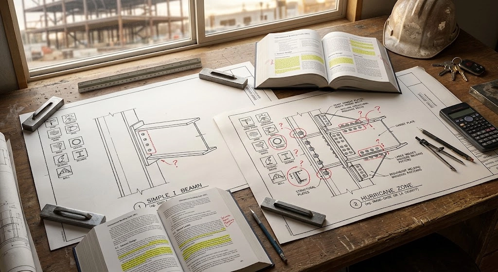
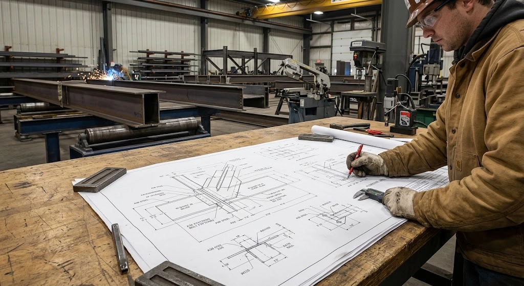
Structural shop drawings show how the frame, connections, and rebar get built and put up. Steel shops, rebar suppliers, and precast makers create these drawings. They follow the structural engineer’s design. The drawings show connections, weld marks, plate spots, and bent rebar shapes. Structural construction drawings need a stamp from a licensed structural engineer before work can start in most states.
Connections come in two main types: shear and moment. Weld marks follow AWS rules. They show weld type, size, length, and spacing. Some welds also need testing, like ultrasonic testing (UT) or magnetic particle testing (MT). Rebar drawings follow ACI rules. They list the bar size, count, shape, and how much it must overlap the next bar.
Why Are Structural Shop Drawings Non-Negotiable for Safety?
Structural shop drawings are a must because an error in the load path can cause the structure to fail.
- Connection details carry real force between beams, columns, and footings.
- Weld and bolt notes decide if a joint can hold its full load.
- Inspectors use shop drawings to know where to test welds, bolts, and concrete.
- Camber notes stop long steel beams from sagging.
What Do the Architectural Drawings Contain?
An architectural shop drawing set has nine main parts.
Site Plan
The site plan shows where the building sits on the lot. It shows property lines and entry points. It confirms setbacks and grading before work starts above ground.
Floor Plans
Floor plans show each room, wall, and size on every level. Crews use them to place walls and plan rough-in work.
Reflected Ceiling Plans
A reflected ceiling plan (RCP) shows the ceiling as seen from below. It maps tile grids, lights, and vents. It puts tiles, access panels, and sprinklers on one drawing so they line up.
Building Elevations
Elevations show each outside wall of the building. They show materials, windows, and height lines. Fabricators use them to check panel size and joint spots.
Building Sections
A building section cuts through the building from top to bottom. It shows floor heights and wall layers. It shows how parts stack from the ground to the roof.
Wall Sections and Details
Wall sections zoom in on one wall. They show insulation, flashing, and how parts are fastened. These details stop water leaks and heat loss.
Door and Window Schedules
Schedules list every door and window by tag, size, hardware, and fire rating. A missing fire rating can fail an inspection.
Finish Schedules and Interior Elevations
Finish schedules match each room to its floor, wall, and ceiling material. Interior elevations show where cabinets and millwork go on each wall.
Code Compliance Notes and Schedules
Code notes list the building use, exit width, and ADA rules for each sheet. Inspectors check these notes during plan review.
What Do the Structural Drawings Contain?
A structural shop drawing set has seven main parts.
Foundation Plan
The foundation plan shows footing size, pier spots, and rebar layout below ground. Frost depth in cold states changes how deep the footing must go.
Framing Plans
Framing plans show beams, joists, and columns on each floor. Fabricators use them to cut steel or wood to the right length.
Shear Wall Plans and Schedule
Shear wall plans mark walls that fight wind and earthquake forces. The schedule lists the sheathing, nail pattern, and hold-down hardware for each wall.
Structural Details
Structural details zoom in on one connection, like a beam meeting a column. They show weld size, bolt pattern, and plate thickness.
Column and Beam Schedules
These schedules list every column and beam by mark, size, and grade. A fabricator checks this list against the framing plan before cutting steel.
General Structural Notes and Specifications
General notes list the design loads, material strength, and code year used on the job. They apply to every sheet unless a detail says something else.
Structural Calculations
Calculations show the math behind each member size and connection strength. Building departments ask for these on deferred items like trusses.
What Are the Main Differences Between Architectural and Structural Drawings?
Architectural drawings define space and finish. Structural drawings define load path and safety. The table below shows both side by side.
| Factor | Architectural Shop Drawings | Structural Shop Drawings |
| Main Focus | Finishes, layout, and look | Load path, connections, and safety |
| Codes Used | IBC Ch. 7, 8, 10, 14; ADAAG; NFPA 101 | IBC Ch. 16-22; ASCE 7; AISC 360; ACI 318 |
| Who Makes It | Millwork, glazing, drywall crews | Steel, rebar, and precast fabricators |
| Who Reviews It | Architect of Record | Structural Engineer of Record |
| Key Data Shown | Hardware, fire ratings, finish schedules | Weld symbols, bar sizes, joint strength |
| Risk if Wrong | Code issue, occupancy delay | Structural failure risk |
How Do Architectural and Structural Drawings Relate to Each Other?
Shared Coordination Points
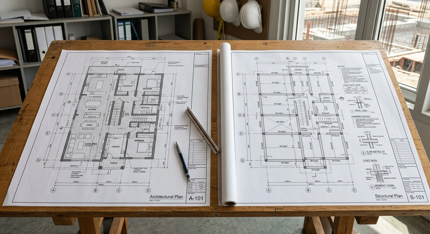
Architectural and structural drawings overlap in a few spots. These include slab edges, wall openings, and ceiling height. A beam’s depth on the framing plan sets the ceiling height on the RCP.
Clash Prevention Through Cross-Review
Design teams overlay both drawing sets before they submit them. According to the National Institute of Standards and Technology, poor data sharing between teams costs the U.S. building industry about $15.8 billion a year. Good coordination at the shop drawing stage catches problems, such as a duct running through a beam, and cuts that loss
Sequencing in the Field
Structural shop drawings get approved and built first. The frame must exist before finishes can attach to it. Architectural crews then follow the structural schedule. They install walls, ceilings, and glass in the right order.
Step-by-Step Workflow for Coordinating Architectural & Structural Shop Drawings
Step 1: Establish the Scope and Target Discipline
Determine whether the incoming submittal targets architectural or structural elements. Identify the core difference right away: architectural sets dictate spatial layouts, interior finishes, and aesthetic details, while structural sets govern load paths, framing members, and physical safety.
Step 2: Review Specific Code Standards for Each Set
Check the applicable code chapters and standards assigned to each drawing type. Verify that architectural details comply with building occupancy codes, fire ratings, and accessibility rules, while structural details meet wind, seismic, and material strength requirements.
Step 3: Draft and Format the Individual Drawing Sets
Separate the drafting process based on trade requirements. Assign millwork, glazing, and drywall teams to produce architectural drawings, while routing framing plans, connection details, and rebar layouts to steel and precast fabricators.
Step 4: Cross-Reference Architectural and Structural Sets Together
Overlay the architectural and structural drawings to catch interdisciplinary conflicts. Compare structural beam depths against reflected ceiling plans and ensure wall openings align correctly to prevent field clashes between structural frames and architectural finishes.
Step 5: Route to the Correct Reviewing Authority
Submit the completed packages to their appropriate reviewers. Send architectural layouts to the Architect of Record and structural packages to the Structural Engineer of Record, ensuring that any deferred items receive the necessary licensed engineering stamps before final approval.
How Do Regional Building Codes Change Shop Drawing Details?
Regional codes change shop drawing details. Seismic risk, wind speed, frost depth, and snow load all differ by place. A drawing set that works in one state can fail plan review in another.
Seismic Design Categories
Seismic Design Categories run from A to F. They come from hazard maps. High-risk states include California and the Pacific Northwest. Parts of South Carolina are high-risk too. In these states, architectural drawings must show seismic joint covers. They must also show flexible partition tops. Structural drawings need extra detail on frames and masonry walls.
Wind Speed Maps and Hurricane Zones
Coastal states need shop drawings built for high wind. Florida and the Gulf Coast can see wind speeds of 180 mph or more. The East Coast can too. These drawings call for impact-resistant glass. This glass is tested under ASTM E1886 and E1996. The drawings also need strong anchors for roof trusses.
Frost Depth and Snow Loads
Cold states need footings placed below the frost line. This stops frost heave. Slab edges also need a thermal break detail. Snowy areas need roof framing built for snow load. This includes even loads and uneven drifts. It also includes rain-on-snow weight.
What Are the Common Challenges in Shop Drawings?
Shop drawing review runs into the same problems again and again.
- Late submittals shrink the review time. This pushes engineers to rush approval.
- Version mix-ups let old drawings reach the shop by mistake.
- Missing sizes or unclear notes cause RFIs. RFIs stall the schedule.
- Local code rules get missed at times. This happens when a team reuses a template from another state. Seismic details in California and wind anchors in Florida are common examples.
- Poor coordination between the two drawing sets causes clashes. These often show up only during install.
- Special inspections can get missed when shop drawings do not mark them clearly. Bolt torque tests and weld checks are common examples.
- A “revise and resubmit” note resets the review clock. It also pushes back the start of fabrication.
- One small construction drawing error, missed at the desk, can cause a big delay once it reaches the field.
Digital Tools Used in Architectural and Structural Shop Drawings
Software platforms vary significantly depending on whether the team is drafting spatial finishes or load-bearing frames. Choosing the right digital environment ensures precise coordination across both disciplines.
For Architectural Shop Drawings
Software like AutoCAD and Autodesk Revit helps technicians model precise interior layouts, millwork, and finish schedules in 2D and 3D formats. These platforms ensure that visual components, window placements, and ADA clearances align seamlessly with architectural codes and design intent.
For Structural Shop Drawings
Specialized programs like Tekla Structures and SDS/2 allow fabricators to model complex steel connections, exact rebar bending shapes, and heavy framing members. These engineering tools calculate exact bolt patterns and plate thicknesses to ensure load-bearing elements meet rigorous safety standards before review.
Why Do You Need Professional Shop Drawing Services?
Professional drafting experts help you avoid costly delays and ensure code compliance.
In-House Limits
In-house drafting teams often juggle multiple concurrent projects, leaving little time to verify every dimension against the latest building codes. A dedicated provider focuses solely on coordination and clash detection. This targeted approach catches critical gaps early, cutting down on rejected packages and lengthy review cycles.
Expert Review
A specialized reviewer checks weld marks, fire ratings, and exact dimensions line by line against contract documents. Pairing this review process with Shop Drawing Service keeps material quantities and build details perfectly aligned since both workflows rely on the same drawing set.
Schedule Impact
A submittal package that passes on the first try keeps the entire construction schedule firmly on track. Conversely, a rejected package forces a costly redesign round that can add one to three weeks depending on job complexity. Projects in high-seismic or high-wind zones face even stricter scrutiny, making early accuracy essential for avoiding major delays.
What Standards Keep Architectural and Structural Drawings Consistent?
Consistent shop drawings use the same code year, units, and symbols on every sheet. Architectural drawings follow IBC Chapters 7, 8, 10, and 14. These cover fire ratings and exit width. They also cover safe glass under CPSC rules. Architectural drawings also follow ADAAG and NFPA 80. These cover access and fire doors. Structural drawings follow IBC Chapters 16 through 22. They also follow ASCE 7 for loads. They follow AISC for steel. They follow ACI 318 for concrete. They follow TMS for masonry.
Both sets must use the same code year. An old code on one set is confusing. It can delay the permit. Fabricators and contractors also expect the same symbols on every sheet. One symbol should mean the same thing on every drawing.
Getting Shop Drawings Right the First Time
Architectural and structural shop drawings do different jobs. But both decide if a building is safe and looks right. Getting them right the first time avoids costly rework, slow permits, and field fights. Firms that need correct, code-checked shop drawings can pair them with strong estimating support. CAD Drafters team can handle both under one process.
Frequently Asked Questions
What is the difference between a shop drawing and a construction drawing?
A shop drawing shows how to build one part. A construction drawing shows the architect’s full design plan. It does not show build details.
Who approves structural shop drawings?
The Structural Engineer of Record approves them. This engineer checks connections, sizes, and code rules before work starts on site.
Why do shop drawings need a PE stamp?
Deferred items, like trusses, need a PE stamp. The stamp shows a licensed engineer checked the design for safety and code rules.
Can architectural and structural shop drawings conflict?
Yes, they can clash at shared spots, like ceiling height or wall openings. Teams overlay both sets before submittal to catch this early.
How long does shop drawing review usually take?
Review time depends on the project size. Simple packages take about a week. Complex steel packages can take three to four weeks.