Ductwork Shop Drawing Services
We’ve all been there: a crucial duct shop drawing is late, and the labor sits idle. It’s the worst. In fact, 78% of contractors report project delays in the past year, often blaming submittal bottlenecks. Hiring professional CAD Drafters for accurate ductwork shop drawing services upfront can prevent this headache. Don’t let poor drawings derail your job; fix it now with us!
20+
Years of Experience
1000+
Satisfied Clients
2000+
Successful Projects
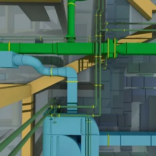
Advanced BIM & CAD Solutions for Ductwork Shop Drawings
Using advanced BIM and CAD technology, we make ductwork shop drawing services faster and more accurate. Our 3D models and detailed plans clearly show every duct run. This approach catches issues early, saving time and money on the construction site.
Level of Development (LOD) 400 Ductwork Modeling
At LOD 400, our ductwork models are detailed enough for fabrication. We define every size, shape, and connection so your labor can build from the plan with confidence.
Integrated BIM Coordination and 3D Modeling Services
We coordinate our ductwork model with plumbing, electrical, and structural plans, catching conflicts early. This integrated 3D BIM approach ensures everything fits and saves time, money, and headaches on site.
Automated Clash Detection & Interference Resolution Reports
Automated clash detection with tools scans your 3D ductwork drawings for conflicts. We supply interference reports showing each clash and suggested fix. This catches issues early, avoiding costly rework.
Seamless Transition from Design to Production
Using Revit’s fabrication tools, we convert duct models into shop-ready drawings, sizing and tagging every part for prefabrication. This digital handoff cuts manual detailing and moves your design to production faster.
Coordination for Multi-Trade Spatial Efficiency
As a trusted ductwork shop drawings company, we use Navisworks to merge models of all trades. 3D coordination reveals spatial conflicts so we can optimize layouts and save space on site.
Point Cloud-to-BIM for Retrofit and Renovation Projects
Using point cloud scans, we build a 3D model of existing ductwork. This precise layout shows every duct and obstacle so that you can plan renovations with no guesswork or surprises.
SMACNA-Compliant Duct Layouts & Standards Documentation
Our SMACNA-compliant documentation turns drawings into buildable work. Using clear duct layout drawings, we translate design intent into fabrication-level detail, so shops and field labor know exact sizes, joints, and clearances. That reduces RFIs, inspection holds, and on-site guesswork.
Furthermore, technical specifications include pressure class validation from ±0.5 to 10 in. w.g., seal class callouts (A, B, C), and automated gauge and reinforcement calculations. We specify transverse joints (TDC/TDF/S&D) based on SMACNA pressure classes and environmental requirements for long-term performance.
Our material callouts cover G90 galvanized, 304/316L stainless, or aluminum with coating and finish notes. Hanger spacing, SMACNA-approved bracing, and seismic support are integrated into every sheet to meet ASCE requirements. Furthermore, our precise submittals and coordination make our ductwork shop drawing services go-to for inspectors and fabricators. If you are one of them, hire is to experience the difference!
Types of Ductwork We Make Shop Drawings For
Galvanized Steel
Galvanized steel rectangular and spiral ducts follow ASTM A653 with G60/G90 coatings. We size gauges from 26 to 16 ga, specify transverse joints (TDC, TDF, S&D), and assign SMACNA pressure classes up to 10″ w.g., ensuring fabrication tolerances and corrosion protection for commercial HVAC systems.
High-Performance Grease Duct
Our high-performance grease duct shop drawings meet NFPA 96. We specify heavy carbon steel (16 ga) or stainless (18 ga), continuous external welds, and fire-rated enclosure clearances. Our ductwork shop drawing services include access panels, grease extract points, and installation sequencing to satisfy inspectors and kitchen fabricators.
Stainless Steel & Specialty Alloys
For stainless and specialty alloys, we detail 304/316L grades and aluminum options. Our drawings call out liquid-tight longitudinal seams, AWS-certified welding symbols, and corrosion allowances. These specs are tailored for lab exhaust, corrosive environments, and hygienic installations where leak-tight joints and weld quality are non-negotiable standards.


Tailored Shop Drawings for Ductwork & HVAC Projects
We tailor shop drawings for every project size, from one-room retrofits to large MEP builds. Our ductwork shop drawing services slot into your schedule, align with equipment schedules, and include fabrication-ready tags and BOMs. That reduces field changes, accelerates prefabrication, and keeps the project on time and on budget with predictable costs and fewer delays.
Duct Fabrication Drawings
Duct fabrication drawings are the shop-floor bible for fabricators. They break systems into buildable spools: straight lengths, elbows, transitions, with exact dimensions. Each piece is tagged and nested, with cut lists and notch patterns. Weld symbols, flange details, and AWS callouts are included for fabrication compliance. CAD Drafters' outputs support CNC nesting and plasma cutting. Our duct fabrication drawings show bend allowances, blanking patterns, flanges, gaskets, and assembly sequences so spools arrive ready to fit—that level of detail cuts shop hours and field rework.
HVAC Duct Shop Drawings
HVAC shop drawings coordinate the duct system with equipment, piping, controls, and electrical connections. They show AHU locations, curb details, chase penetrations, and interface points for piping and wiring. Our sets include equipment schedules, control points, sequence of operations, and coordination notes for commissioning. We run clash detection, update RFIs, and revise layouts so the contract documents align with field reality. These HVAC duct shop drawings simplify permitting and speed approval cycles with clear callouts and referenced standards. BIM exports make handoffs to trades and fabricators efficient and reduce delays.
Trusted Clients


What is Included in Our Ductwork Shop Drawings
- Duct Sizes & Dimensions
- Duct Routing & Centerlines
- BOD & TOD Elevations
- SMACNA Pressure Classes
- Material Gauge Thicknesses
- Transverse Joint Types
- Longitudinal Seam Details
- Fittings & Geometries
- Bill of Materials
Our Clients’ Reviews


Use Our Specialized Sub-Services For Better Results
What Sets Our Ductwork Shop Drawings Apart
Precision is our standard. Our ductwork shop drawing services achieve a 99% clash-free rate using Navisworks and deliver LOD 400 fabrication models. We follow SMACNA rigor and provide 24–48 hour RFI responses, keeping fabrication and field schedules tightly aligned and predictable.
Our HVAC duct shop drawing services reduce material scrap by 15–20% through precise BOMs and pre-fab spool planning. Native Revit workflows sync with MEP models, and seismic and ASCE 7 expertise ensure installations meet code in high-risk zones nationwide coverage.
As an outsourced ductwork shop drawing services partner, we handle NFPA 96 grease duct detail, automated takeoffs that cut estimating time by 40%, LEED material tracking, and VDC-led coordination. We adapt to shop machinery, including Cypcut or Vulcan, so fabrication runs without stoppages.
Our quality controls include ISO-aligned reviews, AIA layering standards, and +/-1/8″ scan-to-BIM accuracy for renovations. Dedicated PMs, cloud collaboration, AWS welding callouts, and over 500 completed projects mean faster approvals, near-zero field rework on complex healthcare, data center, and high-rise jobs.
The Projects We Worked On
Commercial Buildings
Residential Buildings
Government Structures
Hotels and Resorts
Industrial Buildings
Historic Architecturals
FAQs
What is SMACNA in ductwork?
SMACNA stands for the Sheet Metal and Air Conditioning Contractors’ National Association. Its standards define how ductwork should be built, including pressure classes, gauges, joints, reinforcements, and sealing, so systems perform safely, efficiently, and pass inspections.
Who reviews the drawings before delivery?
Every drawing passes a multi-level quality review by senior drafters and BIM leads. We verify dimensions, standards, coordination, and constructability before issuing any set for fabrication or construction.
What file formats do you deliver?
We deliver DWG, PDF, and Revit models as required. Files follow AIA layering standards and client naming conventions, making integration with existing BIM workflows and shop software straightforward.
Are revisions included?
Yes. Revisions related to coordination, RFIs, or design clarifications are included within scope. We track changes clearly so fabricators and field teams always work from the latest approved set.
What do you need to start ductwork shop drawings?
We need contract drawings, specifications, equipment schedules, and architectural backgrounds. If available, coordination models help. Once we review inputs, we confirm scope, pressure classes, and standards before drafting begins.