In construction, one must stay ready for increased budgets if one has ignored many things during planning. Your floor plan is showing a room, but it is not showing the wall height; this is the scenario that can lead you to experience cost overruns.
Well, shows one side of a building in a straight-on view, with actual heights and proportions. And when everyone shares that picture, bids, permits, and builds get smoother. Let’s explore more about elevation drawings, starting with their basic definition!
What are Elevation Drawings?
Most teams use an elevation drawing to show one building side in 2D. You must look straight at the wall so that you can read heights, openings, and proportions. Unlike a floor plan’s top-down view, this view tracks vertical surfaces, ensuring that you can efficiently confirm rooflines, sill heights, finishes, and grade transitions early.
What is Orthographic Projection in Elevation Views?
An elevation view uses orthographic projections to confirm that parallel lines stay aligned. That choice removes perspective distortion, which keeps dimensions reliable for construction projects. Orthographic views also support detail and measurement better than pictorial views. Using these views, you can scale, annotate, and cross-reference sheets with less confusion.
Coordination with Other Drawings
In an architectural elevation drawing, you can professionally coordinate plans, sections, and elevations to match. When a window shifts in plan, you shift it here too. That alignment helps you save time later, because trades stop interpreting intent in the field.
Exterior Elevations Vs Interior Elevations Vs Detail Elevations
Three names play a big role in the world of elevation drawings: exterior, interior, and detail. Let’s explore information on each, as well as the difference between them!
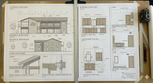
● Exterior Elevations
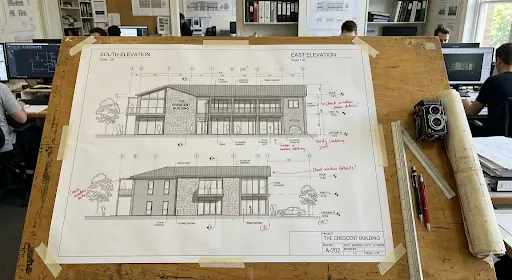
Exterior elevations show outside faces, including facades, materials, and opening locations. They help you judge proportions from the street, plus how the site frames the project. Furthermore, they support facade decisions, like cladding layouts, trims, and window placement.
Types of Exterior Elevations Drawings
There are 4 types of exterior elevation drawings: North, South, East, & West.
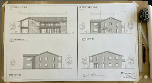
| Types of Exterior Elevation Drawing | What Do They Show? |
| North Elevation Drawing | The rear of the building |
| South Elevation Drawing | Front elevation of the building, usually containing the main entrance |
| East Elevation Drawing | One of the side profiles of the building |
| West Elevation Drawing | The other side profile often displays roofline details and vertical, scaled measurements from the ground plane. |
● Interior Elevations
Unlike exterior views, interior elevations focus on single walls inside rooms, like kitchens and restrooms. They place cabinetry, fixtures, appliances, and finish breaks at real heights. Using this, you can ensure that installers follow one reference, instead of inventing layout rules on site.
● Detail Elevations
In construction, detail elevations zoom into tricky zones, like entrances, balconies, and stair landings. You draw them larger, validate that trade experts can read junctions, edges, and tolerances clearly. That larger scale supports constructability when standard views look too small.
And if you need a full-drawing set map, read our guide: Architectural Drawings: A Definitive Guide to All 13+ Types, Technical Standards, and Modern Digital Workflow.
Why Elevation Drawings are Important in Construction?
In the construction world, elevation drawings play a role in winning the game. Explore its benefits below!
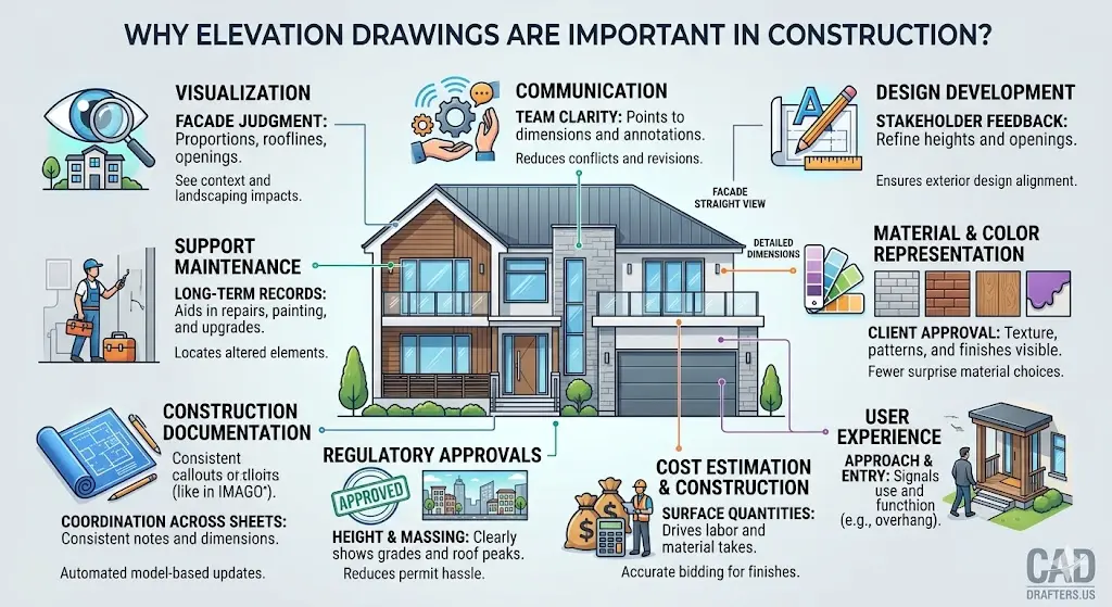
● Visualization
Visualization starts when an elevation drawing shows the facade straight. Using them, you can judge proportions, rooflines, and openings before ordering materials. Furthermore, you see how landscaping and neighboring context shape first impressions.
● Communication
Communication gets easier because teams share one vertical reference in the form of elevation drawings. Instead of debating intent, these drawings enable you to point to dimensions, notes, and tags. That clarity helps everyone align across phases and revisions, reducing conflicts and waste of money.
Note: If you are struggling with the smooth coordination and want to fill the gap between design and technical execution of the project, rely on architectural engineering services offered by the industry experts.
● Design Development
Design development support revisions that you make after stakeholder feedback. Using the elevation views, you can adjust wall heights, roof pitch, and openings, ensuring that the exterior reads right. That revision matters because small elevation choices change the cost and constructability of the project.
● Material & Color Representation
Material and color representation work better when you show textures on the facade. Elevations show finishes and patterns that plans rarely communicate well. This way, clients approve siding, masonry, or panels with fewer late-stage surprises.
● User Experience
User experience shows up in approach views, entries, and how the building signals are used. For example, an overhang can mark an entry without signs or arrows. Using elevation design, you can confidently design for movement and comfort, not just a pretty front graphic.
● Cost Estimation & Construction
Cost estimation and construction start early because surfaces drive quantities and labor time. A detailed elevation drawing supports cost bidding for cladding, paint, openings, etc. Using these drawings, estimators validate scale and measure lengths & areas for reliable takeoffs.
● Regulatory Approvals
Regulatory approvals often require elevations for height, massing, and streetscape impact. Therefore, your sheets must show grades, roof peaks, and any projections clearly. This way, your sets can reduce permit hassle and reduce late redesign loops.
● Construction Documentation
Construction documentation needs consistent dimensions, callouts, and references across sheets. Using elevation views, you can coordinate openings, schedules, and notes, then publish controlled PDFs for teams. Viewport-based workflows also update drawings when the 3D model changes.
● Support Maintenance
Support maintenance because owners need records for repairs, repainting, and upgrades. An elevation plan helps teams locate damaged siding or altered balcony edges later. That documentation reduces guesswork years after the original labor leaves the project.
And if you are thinking how to benefit from all these points, read our guide: Mastering Architecture Site Analysis: Professional Diagrams for Every Successful Build.
Core Components of Elevation Drawings
Here is a checklist for the components of elevation drawings you must consider.
- Dimensions and heights
- Doors and windows
- Material and finishes
- Roofline and structure
- Architectural features
- Annotation and notes
- Scales and orientation
How to Draw an Elevation Drawing?
Start by gathering the floor plan, key sections, and door-window schedules. Then set a clear goal, like permit review, bid pricing, or fabrication help. Also, decide the scale early, because every later measurement depends on that choice.
Now follow this practical workflow:
- Draw the baseline using the floor plan’s exterior wall line as your reference.
- Set wall heights from datums, then mark plate lines, sills, and heads.
- Add doors and windows in exact locations, using a schedule for unit sizes.
- Draw the roof shape, pitch, and overhangs, and show every visible edge.
- Include decks and railings, plus stairs, canopies, and guard requirements.
- Layer in materials, hatches, and key notes so trades accurately price the scope of work.
- Review the elevation drawing with stakeholders, then capture redlines before rework starts.
- Get final approval, then finalize sheet numbers, dates, and revision tracking.
If you start with an elevation sketch, lock datums early anyway. For a final architectural elevation drawing, add dimensions, finishes, and coordinated tags. Then, export PDFs and share them with estimators and the field team.
Remember that reliable elevation drawings track revisions, so every bidder works on the same version. And if you want concept alignment first, benefit from the professional architectural design services.
Best Practices for Precise & Accurate Elevation Design
● Anchor Datum Lines First
Anchor datum lines first, then dimension from that consistent baseline. This way, you can avoid changing heights when teams revise wall plates and roof peaks. In addition, confirm the scale early, because measurement errors multiply fast on site.
● Show Buildable Architectural Details
Show windows, doors, and rooflines with buildable, readable detail. Include material notes and finish patterns, ensuring that the trades’ scope runs consistently. This speeds house elevation design reviews during design development.
● Coordinate Early with Engineering Teams
Coordinate with structural and MEP teams before your first issue to catch clashes early, like vent terminations, louvers, and canopy supports. After that, lock revisions, because controlled updates reduce rework and field confusion.
Tools & Software Used for Elevation Drawings
The time has gone when traditional hand drawing helped. Today, professional drafters use different tools and software to create elevation drawings.
● CAD Software
CAD software helps control linework, layers, and annotation systems. Standards matter here because they keep files readable across teams and software. The national CAD standard exists to organize and present facility drawing information consistently.
● 3D Modeling
3D modeling helps when you want elevations to update with every model change. In Vectorworks, you can create viewports and add notes and tags as overlays. You can also cut an elevation view by placing the section line correctly.
Note: If you struggle with vertical coordination, streamline your workflow with our guide on Section Drawings in Architecture: The Architect’s Guide to Vertical Space.
● AI-Powered Design Tools
AI-powered design tools help you test options during pre-design and schematic work. For example, Autodesk offers AI-powered tools for early-stage option exploration. You can use them to shortlist house elevation design directions and document them in CAD.
Furthermore, when you model in Revit, material takeoff schedules can list materials per component. That output supports cost control because quantities and costs stay tied to the model. This way, the use of AI-powered tools enables teams to update project scope and estimates faster when design changes occur.
Conclusion
Using elevations to describe vertical surfaces with real heights is the profitable choice for construction experts. In these drawings, you can see exterior, interior, or detail views based on project scope and coordination needs. Furthermore, these drawings enable you to confirm core elements, like openings, rooflines, materials, and vertical datums upfront. This way, you can stick to a tight workflow, review with stakeholders, and control revisions for bidding with confidence.
CAD Drafters supports contractors and project teams with code-aware CAD deliverables. At this company, we produce DWG, DXF, RVT, and PDF outputs, so coordination stays headache-free. Simply put, if you need an elevation drawing that survives estimates and field execution, we can help.
Send your plans, markups, or sketches, and request drafting support today!
FAQs
What scale works best for most elevation sheets?
Most teams use common architectural scales like 1/8” or 1/4” equals 1’-0”. You should pick the smallest scale that still keeps dimensions accurate and readable.
How to handle sloping grades on exterior faces?
Show finished grade lines and key spot heights at critical corners or steps. Next, dimension from a consistent vertical datum, so teams don’t average slopes.
What’s the difference between an elevation and a building section?
Elevations show the face of the project, while sections cut through the building for internal relationships. In other words, sections clarify walls, floors, and ceilings that exterior faces can’t reveal.
Do you need interior wall views for every room?
No, focus on rooms with custom cabinetry, tile layouts, or dense fixtures. That targeted scope saves drafting time, while still preventing install mistakes later.
Which file formats should you request when outsourcing drafting?
Ask for DWG for edits, plus PDF for review and distribution. If you work in BIM, request RVT too, so schedules and updates stay linked.
How to prevent mismatched window tags across sheets?
Use coordinated schedules and tag openings from the same source data. Model-based tagging tools help because tags update when objects change.
Can as-built elevations be generated from photos or scans?
Yes, teams often draft from site measurements, photos, and scan-based references. However, you still need field verification, because photos distort scale and alignment.
How to keep measurement takeoffs accurate from PDFs?
Calibrate the drawing scale to a known dimension before you measure anything. Plus, store measurements as markups, so you can summarize quantities consistently for estimates.