
Picture this. You stand on a bustling construction site in the US. The laborer pours concrete for a new high-rise. Yet you worry. Will that beam hold under wind loads? Will the foundation crack during the monsoon season? One small miscalculation and you face delays, rework, or project failure.
You know that moment when the architect hands over plans and everyone waits for the go-ahead statement. Finite element analysis changes the game. It lets you test designs virtually before anyone lifts a hammer. Using this, you can simulate real-world forces right on your CAD screen. This means no more guesswork since you can catch problems early and deliver stronger builds.
That is exactly why finite element analysis matters to you today. Let’s explore more about FEA!
What is FEA?
Finite element analysis predicts how structures behave under real forces. To achieve the goal of FEA, you break complex parts into tiny elements. Then you apply math to each one. Software solves the equations and shows stress, strain, and deformation.
- You use it every day in CAD drafting. It turns your 3D models into reliable performance forecasts.
- Contractors rely on it to verify load paths.
- Builders use it to avoid expensive field changes.
- Engineers trust the numbers before they approve drawings.
So what is FEA? It is your digital safety net on every construction project.
FEA Vs FEM
People often mix the two terms: FEA & FEM.
What is FEM? Its full form is the finite element method, which is the math behind it all. You divide geometry into elements and nodes. Further, you set up equations based on physics.
Finite element analysis applies this method and interprets the results. Using this, teams run the simulation and study color maps of stress, and then decide what changes to make.
You can say that the finite element method is the recipe and finite element analysis is the finished dish on your table. You need both, but FEA analysis delivers the actionable insights you use in the office.
The History of FEA
Engineers in the 1950s needed better ways to test aircraft wings. So, they developed early finite element method techniques. By the 1970s, software like ANSYS appeared. Computers finally handled the heavy math.
You see the same evolution in CAD today. What started as simple beam checks now simulates entire buildings. Now, professionals run nonlinear studies that once took weeks. This shows that progress keeps accelerating in today’s world.
Yet the core idea stays the same. You divide and conquer complex problems.
Features of FEA
Teams rely on specific tools inside FEA software every day. Here is what they do and why they matter to your workflow.
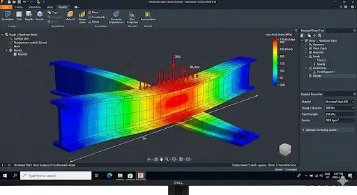
● Nonlinear Static Stress
You can test materials that bend or yield under load. The software accounts for large deformations, and you can see exactly where your steel beam starts to buckle.
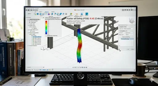
● Structural Buckling
Using FEA, you can predict sudden collapse under compression. The tool gives you a critical load multiplier, so that you adjust member sizes before fabrication drawings leave your desk.
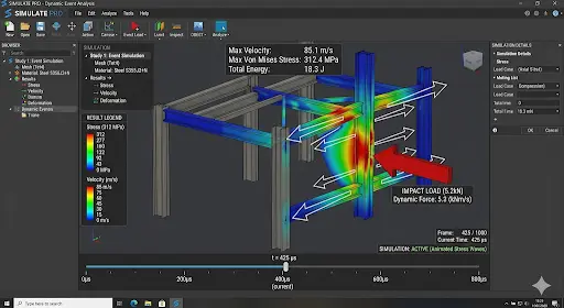
● Event Simulation
This software enables you to model impacts or sudden forces over time. You just need to drop a tool on a scaffold and simulate a seismic shake. Ultimately, you get the structure to respond second by second.
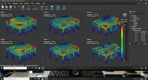
● Modal Frequencies
In this software, you can find natural vibration modes, ensuring that you avoid resonance with wind or machinery. Architects like these results for slender towers.
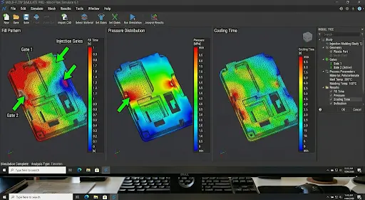
● Injection Molding
This software allows you to simulate plastic flow in molds. In other words, you can predict warpage and sink marks before tooling. Designers use this for custom facade panels.
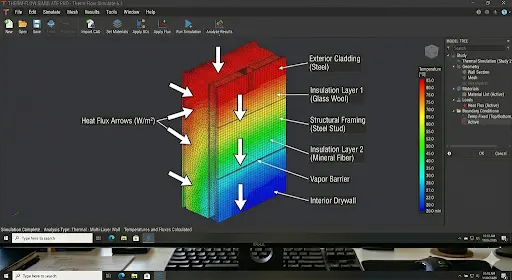
● Thermal Analysis
Using FEA, you can track heat flow through concrete slabs or steel connections. Simply put, you can prevent cracking from temperature swings in the US climate.
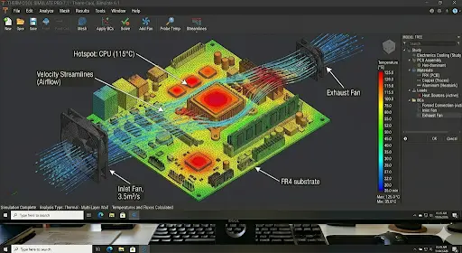
● Electronics Cooling
Using this tool, you can model heat dissipation in control panels mounted on site equipment. Furthermore, you can keep components safe in hot job-site conditions.
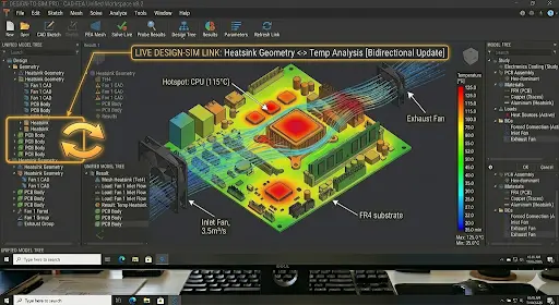
● Integrated CAD Workflow
This software helps you stay inside the same model. You just need to change geometry once, and the results update instantly. This means no file exports and no chances of lost data.
The Benefits of FEA
You can experience real advantages when you run finite element analysis early.
- It improves the design to appear naturally. Using this, you can see weak spots and fix them before the shop drawings.
- Digital prototyping replaces physical mock-ups. Today, teams test 10 options in the time it once took to build one.
- This tool offers visualization, which makes results crystal clear. This means you can show clients color maps instead of spreadsheets.
- Using this, you can assess complex geometries that hand calculations cannot touch.
- FEA enhances insight into critical design parameters that guide every decision. In other words, you can know exactly which thickness saves material without sacrificing building strength.
- Using this, you can access existing experimental results and apply them to new models. This way, validation speeds up for each project you work on.
- This tool offers earlier testing in the development process, which catches issues during schematic design.
- Utilizing FEA, you can simulate a range of physics at once, including stress, thermal plus vibration.
- Its testing variety lets you explore wind, seismic, and live loads in one session.
- Furthermore, you can optimize alternative designs quickly by comparing costs and performance side by side.
- You can save time, money, and resources using FEA, as this ensures fewer change orders on site.
- This software is famous for increased productivity and revenue follow-up. This means you can deliver faster and win more bids.
How does Finite Element Analysis Work?
Follow three clear steps every time.
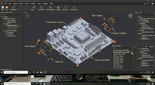
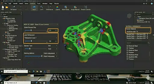
1. Pre-Process
- Import the CAD model.
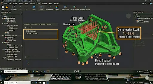
- Assign materials and define loads.
- Set boundary conditions that match real supports.
- Create the mesh.
2. Process
In this stage, the software runs the maths using physics laws, like Hooke’s Law for elasticity. Then, all the individual results are combined to assemble equations. Next, the digital calculator solves the equation to give you results.
![]()
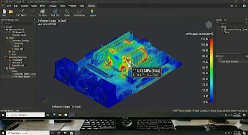
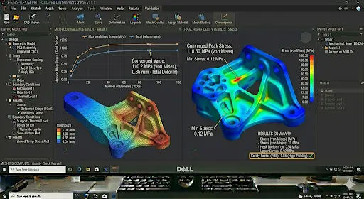
3. Post-Process
Again, come to you.
- Review color plots, graphs, and animations.
- Check convergence and export reports.
- Decide what to change.
Types of Finite Element Analysis Tests
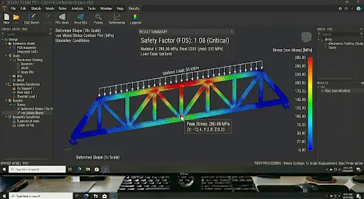
● Static Analysis
In this type of FEA, teams apply constant loads. The structure does not move over time. Using this, you can check deflections and stresses under dead and live loads.
Workflow: Import model → mesh → apply fixed loads → solve → review safety factors.
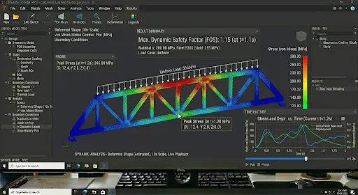
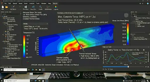
● Dynamic Analysis
This type of FEA analysis allows you to study time-varying forces or vibrations. This means you can model earthquakes or machine vibrations.
Workflow: Define time steps or frequencies → apply dynamic loads → solve transient equations → animate response.
● Thermal Analysis
Thermal analysis helps you track heat transfer and resulting expansion, so that you can prevent cracks in concrete pours.
Workflow: Set temperatures or heat sources → define conduction and convection → solve → view temperature and stress maps.
Static Analysis Vs Dynamic Analysis Vs Thermal Analysis
| Aspect | Static Analysis | Dynamic Analysis | Thermal Analysis |
| Load type | Constant forces | Time-varying or frequency-based | Temperature gradients |
| Time dependency | None | Yes – transient or harmonic | Steady-state or transient heat flow |
| Typical output | Stress, strain, deflection | Vibration modes, accelerations | Temperature distribution, thermal stress |
| Use case for you | Dead/live load checks | Seismic or wind gust response | Expansion joints in hot climates |
| Computation speed | Fastest | Slower, needs more steps | Medium |
How to Convert From 2D CAD to a High-Fidelity FEM Model
You can turn flat drawings into accurate 3D simulations in 6 easy steps.
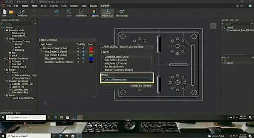
1. Prepare and Import 2D CAD Data
Clean layers and scale the drawing. Next, import DWG directly into the FEA environment.
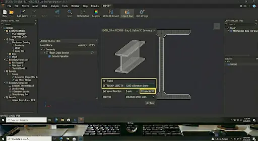
2. Convert 2D to 3D Geometry
Extrude profiles and add thickness, and then create solid bodies from lines.
Note: You can also rely on 2D to 3D Conversion Services from the industry experts, saving your time and effort.
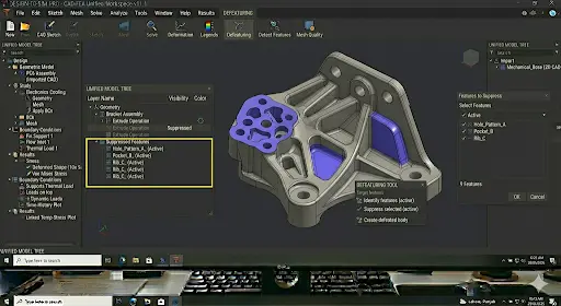
3. Simplify & Defeature Geometry
Remove tiny fillets and holes that do not affect the results while ensuring that you keep the analysis fast.
4. Mesh and Material Assignment
Next, create a fine mesh, and assign concrete, steel, or rebar properties from your library.
5. Boundary Conditions and Load Application
Then, the pin supports and adds wind or seismic loads. Plus, match site conditions exactly.
6. Validation
Last, run a coarse mesh first, then refine until results stabilize and compare it to manual calculations.
The Role of FEA in Modern Engineering
- Virtual Prototyping & Cost Reduction: You can build digital twins first, and then reduce prototype costs by 70% on average.
- Performance Prediction & Validation: You can understand exactly how the structure performs before concrete is poured.
- Design Optimization: You can iterate shapes and sizes inside the same model. Furthermore, you can reduce material while meeting codes.
- Enhanced Safety: You can simulate failure modes that field tests cannot safely replicate.
Common Challenges & Best Practices Related to Finite Element Analysis
● Mesh Convergence and Quality
You know how coarse meshes give wrong answers. You can refine until results change by less than 5%. Plus, always check element quality metrics.
● Boundary Conditions and Constraints
According to industry experts, wrong supports create artificial stiffness. You can solve this issue by double-checking against actual foundation details every time.
● Singularities and Stress Concentrations
Sharp corners increase stress unrealistically. Do you know how you can avoid this? Fillet edges or using sub-modeling are the solution, as you can get realistic numbers using them.
● Convergence Issues (Non-linear Analysis)
Large deformations in designs make the teams struggle. You can use smaller time steps and enable automatic stabilization to avoid this problem.
● Misinterpretation of Results
Colorful plots look impressive but mean nothing without context. Therefore, you must always verify units and compare them to known benchmarks.
The Future of FEA
- AI and Machine Learning Integration: AI suggests optimal mesh density before one clicks solve. This means you can finish your studies faster.
- Real-Time Simulation: Professionals drag loads and watch live updates and changes appear instantly.
- Cloud-Based & Democratic Access: You can run heavy simulations on your laptop through the browser; this means no more expensive workstations.
- Automation and Smart Meshing: Software creates perfect meshes automatically. This way, you can focus on results instead of modifying elements.
- Multi-Physics and Digital Twins: You can couple structural, thermal, and fluid behavior in one model. The digital twin gets updated with sensor data from the actual building.
- Hardware Evolution: GPUs and quantum-inspired professionals cut solution time from hours to minutes. This means you can deliver reports the same day.
Don’t let mesh errors or wrong constraints ruin your designs. Get expert FEA validation today.
Commonly Asked Questions
What are the disadvantages of FEA?
You need accurate material data and boundary conditions; otherwise results will mislead you. Complex models demand powerful computers and training time.
Where does FEA use in the real world?
You can see it on bridge load ratings, high-rise wind studies, seismic retrofits, and equipment foundation designs. Contractors verify shop drawings; architects optimize curtain walls; builders avoid costly surprises during erection.
Can you do FEA by hand?
You can solve very simple beams or plates manually using basic equations. However, real structures with irregular shapes and multiple loads demand software. In other words, hand calculations serve only as quick sanity checks.
Conclusion
You now understand what finite element analysis really is, plus how to run it, when to use each type, and how it fits inside your CAD workflow. Furthermore, you have explored how FEA can benefit you. So rely on this option for perfect designing. And if you need expertise to operate FEA, you must rely on experts who are already pro in this software.
At CAD Drafters, we turn these insights into practical drawings every day. We prepare clean 2D to 3D models ready for your FEA studies. Our team delivers accurate shop drawing services that match simulation results perfectly.
Ready to bring finite element analysis into your next project? Drop us a message today. Let us help you build smarter, safer, and faster. Your next successful handover starts here.