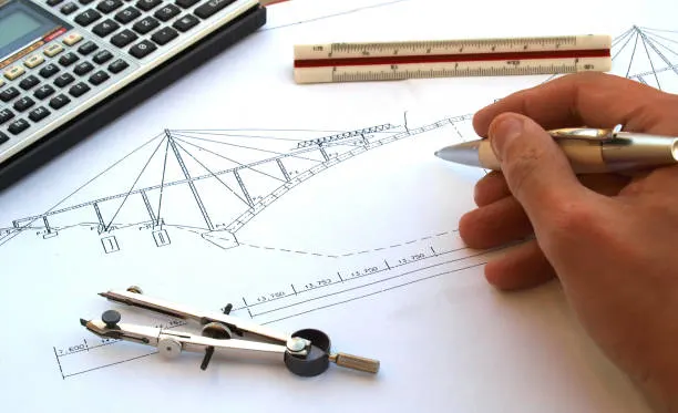
All construction projects that get messy on-site commonly have issues with the drawing. You might have ignored a broken wall or missed a bolt, thus experienon-sitecing issues on site. It is where engineering drawings address many of the on-site construction issues. Let’s understand the concept of these drawings in detail below!
What are Engineering Drawings?
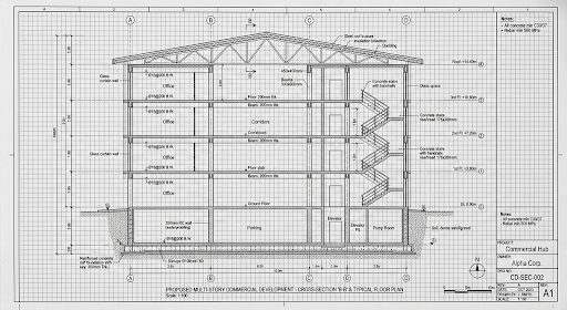
Engineering drawings, also called mechanical drawings, blueprints, detail drawings, and technical drawings, are highly detailed technical diagrams. They are used to comprehensively define the geometric and manufacturing notes of structures. They describe:
- What to build
- How to build
- Where tolerance matters
All the above questions are answered when you get details on:
- Shape
- Size
- Location
- Material
- Acceptable variation
For engineers, architects, and manufacturers, they work as a universal graphical language, ensuring seamless design communication across different languages and regions.
Three Basic Functions of Engineering Drawings
- It communicates geometry.
- It records intent.
- And it gives other trades one reliable reference.
What are the Key Types of an Engineering Drawing?
As a construction sector professional, you know that different jobs need different drawings. Therefore, experts rely on different types of detail drawings that include the followings:
- Civil engineering drawing focuses on site work, grading, roads, and utilities.
- Electrical engineering drawing maps circuits, panels, and connections.
- Structural engineering drawings cover members, connections, and load paths.
- Mechanical engineering drawing handles parts, assemblies, and motion-based systems.
- Geometric drawing focuses on form, proportion, and construction logic.
Each type answers different questions, leading building teams towards seamless construction.
The Game of Angles in Technical Drawings
Here comes the outer and inner views. As a construction team member, you need both for outcomes your client asks for.
Outer Views
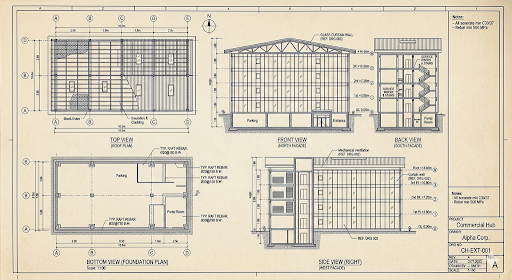
From outside, you can see the structure from the following angles:
- Front
- Back
- Top
- Bottom
- Sides
Each angle tells a different story regarding dimensions.
- Front: Width x Height
- Back: Width x Height
- Top: Width x Depth
- Bottom: Width x Depth
- Sides: Height x Depth
Inner Views
When you want to see inside the face, you see 3 views in engineering drawings:
- Section Views: This cuts through the object and shows what sits inside
- Crop Views: This removes everything unneeded around the detail
- Break Views: This shortens a long shape while preserving scale in the useful zone
What are the Core Components of Engineering Drawings?
These technical drawings carry information that makes a plan buildable. Let’s see what information is hidden under this umbrella.
-
Geographical Views
These representations project a 3D object onto a 2D sheet, showing an image from 3 angles:
-
- Orthographic Views: This shows top, front, and side views.
- Isometric Views: This shows the rotated angle of the object, covering width, height, and depth.
- Sectional Views: This shows internal features and hollow spaces inside the object.
-
- Auxiliary Views: This shows horizontal, frontal, or profile views of the object.
- Detail Views: This shows the internal features of the object in an enlarged form.
- Broken-out Views: This reveals internal features of the object after cutting.
- Exploded Views: This shows how multiple individual components fit together.
- Partial Views: This only draws the portion of the object that contains the necessary features.
-
Visible/Object Lines
When you see an engineering drawing sheet, you see different lines, which all mean different things. This means misreading the one can ruin the whole plan. And when you know how to read lines in blueprints, you experience drawings that are readable and consistent.
See the table below to get the visuals of each line.
| Line Type | Appearance |
| Continuous Line | Thick, unbroken, solid |
| Hidden Line | Thin dashes |
| Cutting Plane Line | Thick dash-dot |
| Center Line | Thin alternating long-short dashes |
| Dimension & Extension Line | Thin solid |
| Broken View Line | Irregular zigzag |
What Each Line Means in a Technical Drawing Sheet?
- Continuous Line: This line shows visible edges, outlines, and major boundaries. It gives the reader the first clear shape of the object.
- Hidden Line: This dashed line shows features that exist but stay out of sight from that view. It helps readers understand what the surface hides.
- Cutting Plane Line: This line marks where a section view cuts through the object. It tells the reader exactly where the inside view begins.
- Center Line: This alternating dash pattern marks axes, centers, and symmetry lines. It is used whenever holes, round features, or balanced parts appear.
- Dimension & Extension Line: These lines connect the feature to its measurement. They show exactly what size or position the note describes.
- Broken View Line: This line shortens a long object without changing its proportion in the important area. It saves space and keeps the sheet clean.
-
Dimensions and Tolerances
Dimensions translate how big the part should be, and tolerances guide how much variation you can accept. This is a minor difference that answers whether 2 parts fit on site or not. Geometric tolerances, or GD&T, go deeper. They control flatness, straightness, perpendicularity, and location. And that precision helps engineers keep assemblies from failing during fabrication or installation.
-
Notations and Text
Notes carry the information that geometry can’t carry.
- General notes can ask for rough edge removal, coating, or cleanup.
- Material notes define the exact metal, plastic, or alloy.
- Surface finish symbols show how smooth a surface must be.
Coming to text, they remove guesswork from engineering drawings. Something you are not getting from the shape alone is answered by the text in the blueprints. Simply put, text keeps the drawing and engineering aligned when multiple teams handle the same project.
-
Layout and Identification Blocks
First, get their components: Title Block, Bill of Materials (BOM), Revision Block, Drawing Border and Zones, all carry different functions as mentioned below.
| Element | What does this include? | Benefit |
| Title Block | Holds the name, part number, scale, projection angle, material, and author details | Brings immediate context and accountability |
| Bill of Materials (BOM) | Lists every subcomponent and fastener | Streamlines procurement and assembly |
| Revision Block | Tracks changes, dates, and version history | Ensures total version control and traceability |
| Drawing Border and Zones | Helps teams locate features quickly on large sheets | Enables rapid navigation on large or complex sheets |
What are Standards and Conventions in Technical Drawings?
It is where a common language for all team members is provided, and this job is done by standards and conventions in blueprints.
- Standards set the official rules for sheet sizes, projection, units, and tolerances.
- Conventions give users accepted shortcuts for threads, gears, symmetry, and sectioning.
Regarding their authorities, “>ISO guides global practice, and “>ASME mostly shapes North American practice. The aim of both platforms is the same: Reducing confusion so that drawing and engineering can cross borders without turning into a translation problem.
Additionally, ISO standards, along with BS 8888, align dimensioning, tolerancing, and documentation in engineering drawings. This ensures consistency when drawings shift from office to factory, eliminating the risk of losing meaning.
Top 3 Mistakes Linked with Engineering Drawings
Technical Engineers commonly make the following mistakes during the building blueprints, including the followings.
-
Missing or Confusing Scope
If you are considering “install as required” as a specification, it is not; it’s totally a missing and confusing work scope statement. Why? Because there is no complete information on material grades, weld sizes, surface finishes, and coating types in it. This force fabricators and installers guess that they always carry a bundle of problems.
-
Improper Dimensioning
It is where many engineers make their first big mistake during drawings. If dimensions conflict or repeat without reason, your team starts guessing when it comes to shop floors. If not resolved on time, this delays the project and also increases the project cost unexpectedly.
-
Undisciplined Lines
Hidden lines, centerlines, and cutting lines all need discipline. Many engineers make this mistake; they draw a visible line at the place of a hidden line unintentionally. Consequently, fabricators build incorrectly, wasting both time and money.
What Software & Tools Engineers Use for Blueprints?
Traditional drafting is limited to basic sketching and teaching today. Different engineers use different digital tools, from general 2D drafting to cloud-based modeling. Mechanical teams rely on solid modeling; aerospace and automotive groups need tight parametric control; civil, structural, and architectural engineers need dependable documentation. They all fulfill their requirements using the engineering tools and software.
Here are the most common digital platforms engineers rely on during drafting.
- AutoCAD: It is a common choice for general and 2D drafting.
- Autodesk Inventor: This supports mechanical parts and assemblies.
- Autodesk Revit: This helps with architectural and building documentation.
- Autodesk Fusion 360: It helps in combining design, modeling, and collaboration.
- Drafting Boards and T-squares: They serve hands-on layout work and early training.
Note: Software never replaces judgment. It only speeds up the work of drawing and engineering when you provide it with accurate inputs. This means the source of accuracy is you.
How do Engineering Drawings Benefit Construction?
-
Improved Project Coordination
Engineering drawing improves communication first. Teams stop interpreting the same sketch in five different ways. This shows benefits on the job site; there are no chances of loose assumptions that can delay trades, badly affecting the drawing and engineering coordination.
-
Increased Cost Efficiency
With precise and accurate detail drawings, you can control project cost better. How? A clear engineering drawing reduces waste, excess ordering, and field corrections. In 2026, that is more helpful because freight costs and imported material prices are fluctuating fast after war-related disruptions and shipping detours.
-
Local Code Compliance
Technical drawings also support compliance, quality control, and risk reduction. By relying on right blueprints, inspectors can check the work against a defined standard, installation teams can install with almost no delays, and managers can track project progress without rebuilding the plan from scratch.
Conclusion
So when you have solid engineering drawings for a construction project, you not only get details on parts, but you also get support with budgeting, scheduling, margin protection, and building quality. And the game starts when you are on sheets, not the site. This enables you to spend significant time and money to invest in the next project.
What if you lack expertise in engineering drawings or don’t have time for blueprints? You have a reliable option of outsourcing engineering services, and this is where CAD Drafters stands apart from other firms in the US. By combining human and digital power, we provide engineering drawings that streamline the phases down the road. Contact us for a detailed discussion of your particular project.
Get Engineering Drawings that Eliminate Hassles on the Construction Site!
FAQs
What do orthographic projections show in an engineering drawing?
Orthographic projections show an object through flat, true-to-size views. They include front, top, and side views.
What are BS 8888 and ISO standards?
BS 8888 is a British standard framework for technical product documentation. ISO standards set broader international rules for dimensioning and tolerancing. Both make an engineering drawing easier to read across teams and regions.
What if a blueprint lacks a clear reference system for measurement and control?
This is named as Poorly-Defined Datum Structures, which lead to variation and inspection confusion. You can avoid that by defining datums based on function, plus verifying them against how the part actually fits on site.
What is the difference between BOM and BOQ?
A BOM lists the parts, fasteners, and subassemblies inside an assembly drawing. On the other side, a BOQ lists quantities for procurement and cost planning. They solve different problems, but both make drawing and engineering organized.