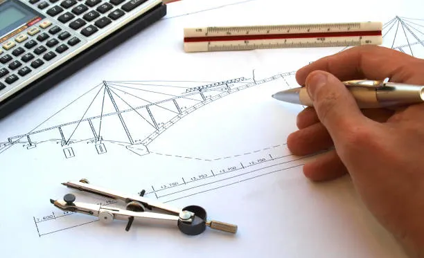
Every building you walk into and every machine you use started as a flat drawing. Before anyone lays a single brick or cuts a part, someone has to show exactly what to build. That is the job of 2D drafting. Even with 3D models everywhere, builders and machinists still work from clear 2D drawings every day.
A solid 2D CAD drawing tells them what to make and what materials to use. This guide walks you through it all. You’ll learn what 2D drawing and 2D design mean, and how 2D CAD drawings are made. You’ll also explore what file types matter and how standards keep work consistent. Real examples include house plans and a 2D car drawing. New to the field? Start here.
What Is 2D Drafting?
2D drafting is the process of designing two-dimensional objects on a plane. Each representation of the object has only two measurements: length and width (also called X and Y). The absence of a depth view does not mean there is no longer a drawing.
In this case, several views, such as the top, front, or side view, will reveal the complete dimensions of the part or the overall shape of the building. In the past, drafters manually drew plans on a drafting board using pencils, T-squares, and compasses. Today, most drafting happens on a computer, which we cover later.
The aim of 2D drafting remains the same. The drafter takes the idea and translates it to a clear set of instructions. The reader of the draft, whether he is a contractor, machinist, or inspector, must be able to construct the product without making assumptions.
The work covers many fields:
- Architecture: plans, elevations, sections, and site plans.
- Mechanical engineering: part drawings, assembly drawings, and tolerances.
- Electrical engineering: wiring diagrams and panel layouts.
- Civil engineering: road designs, drainage designs, and survey drawings.
- Manufacturing: shop drawings, fabrication drawings, and cut sheets.
The industry behind all this is huge. Autodesk’s 2027 State of Design & Make study says that, based on 2026 research, design and make industries employ nearly 296 million people worldwide. Many of them work from 2D drawings as part of their daily work.
What Does 2D Mean in Drawing and Design?
Now that you are aware of drafting, let’s clarify some important terms. If you’re new to this field, you might be curious about “what does 2D flat mean?” In simple terms, “2D” is short for two-dimensional. A 2D drawing shows height and width but no depth. The best examples of this are paper and computer screens. Everything you draw on them looks flat, no matter how much depth the lines suggest.
Here is how a few common terms fit together:
| Term | Meaning | Simple Example |
| 2D | Two dimensions (X and Y) | A floor plan on a sheet |
| 2D drawing | Any flat drawing made by hand or software | A hand sketch of a bracket |
| 2D design | The planning and layout of an idea in flat form | A site layout or a logo layout |
| 2D drafting | Technical, dimensioned drawing for construction or manufacturing | A shop drawing with tolerances |
| 2D CAD drawing | A 2D technical drawing made in CAD software | A DWG floor plan |
2D Drawing vs. 2D Design
Confusion between these two terms is common, so let’s explain. The term 2D drawing refers to the tangible outcome, the resulting paper or image itself. On the other hand, the term 2D design refers to the idea behind the outcome. A 2D designer doesn’t create the drawing itself, but decides how different components should be arranged, after which a drafter produces it.
In real life, an individual will do both jobs, especially on small projects. In big projects, the designer provides an idea of what to do, and the drafter creates a ready 2D drawing.
2D vs. 3D: What Is the Difference?
Once you understand the concept of flat diagrams, the following question is how they relate to three-dimensional shapes. One common question frequently asked in this case is: What is the difference between the 3D and 2D figures? It is simple: depth.
The two-dimensional drawing comprises merely length and width. On the other hand, a three-dimensional model incorporates depth, which makes it possible to spin it around and examine it from all angles.
That does not make one better than the other. They do different jobs.
| Feature | 2D Drawing | 3D Model |
| Dimensions | Length and width | Length, width, and depth |
| Main use | Documentation, permits, shop and site instructions | Visualization, simulation, clash checks |
| Learning curve | Easier to start | Takes more time to learn |
| File size | Small | Often large |
| Edit speed | Fast for small changes | Slower, since parts are linked |
| Typical output | Plans, sections, details | Solid models, renderings, animations |
| Printing | Prints clearly on paper sheets | Needs 2D views made from the model |
Here is an explanation of why 2D drawings remain relevant in the industry, even with the introduction of 3D modeling. Most building departments and inspectors still ask for printed or PDF drawings. 3D modeling alone is not sufficient, as dimensioned sheets are still necessary on the construction site. In several cases, the team constructs 3D models and then derives 2D views from them.
Where 2D Modeling Fits In
The term 2D modeling refers to the construction of figures using basic shapes such as lines, arcs, circles, and polylines. It is the basis of every flat drawing. The skills learned in 2D also apply to 3D modeling. Many 3D models arise from 2D sketches that are extruded or revolved. By developing good habits in 2D modeling practice, such as closed profiles and accurate constraints, you will find the process of producing 3D models simpler.
Types of 2D Drawings: Sketches, Plans, and Detail Drawings
Let’s look at the kinds of drawings you will encounter on a real project after you know the basics in detail. Not every 2D drawing serves the same purpose. A project usually moves through several types, from rough ideas to final construction documents.
2D Sketches
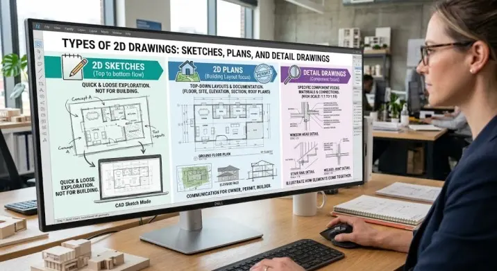
A sketch is a quick and loose drawing used to explore ideas. It may be done on paper or in a CAD sketch mode. Sketches help a 2D designer test layouts before spending time on exact dimensions. They are not meant to be built from.
2D Plans
A plan is a top-down view that shows how a space or object is laid out. This is the most common type of drawing for buildings. Take 2D houses as an example. A typical residential set includes:
- Floor plans showing rooms, walls, doors, and windows
- Site plans showing the lot, setbacks, driveways, and utilities
- Elevations showing the outside faces of the house
- Sections showing a vertical slice through the structure
- Roof plans showing slopes, ridges, and drainage
These 2D drawings let a homeowner, a permit office, and a builder all look at the same information. If you only have a hand sketch or a rough idea, our CAD Drafters team can turn it into a full set through our residential drafting services.
Detail Drawings
Detailed drawings focus on a particular part and illustrate how different elements come together. Some examples of detail drawings include window head details, stair rail details, and welded joints. Detailed illustrations are made at scales, such as 1:5 and 1:10, so that all components and materials can be identified.
Here is a quick comparison:
| Drawing Type | Purpose | Typical Scale | Level of Detail |
| Sketch | Explore ideas | None or rough | Low |
| Floor plan | Show layout | 1:50 or 1:100 | Medium |
| Elevation | Show exterior faces | 1:50 or 1:100 | Medium |
| Section | Show vertical build-up | 1:20 to 1:50 | Medium to high |
| Detail drawing | Show connections and materials | 1:1 to 1:10 | High |
2D Engineering Drawing: Views, Standards, and Rules
Plans and details are common in buildings. In mechanical and product work, the same ideas are subject to stricter rules. Compared to general sketches, 2D engineering drawings are much more formal. A clear system of regulations ensures that anybody can read the drawing the same way after receiving proper training.
Use of Orthographic Projection
Most two-dimensional engineering drawings are based on the orthographic projection technique. This technique reveals the object from different flat perspectives, usually from the front, above, and the right side. Each view corresponds to another. Altogether, the views present a full picture of the object. Some drawings may further include an isometric view, which looks three-dimensional but is still drawn flat.
Standards You Should Know
Standards ensure that drawings are uniform regardless of the team, location, or program used. The most popular standards are:
- ISO 128 in respect of the general drawing standards and types of lines
- ASME Y14.5 in the field of dimensioning and tolerancing
- ANSI/ASME Y14.3 in the domain of multi-view drawings
- AIA CAD Layer Instructions and the National CAD Standard of the United States in the area of architectural layer naming
Using the above standards will make it easier for your drawings to be reviewed, authorized, and produced, while ignoring them will put you at a high risk of costly rework.
Sheet Sizes and Scales
In the U.S., there are common types of sheets, called ANSI sheets. These include types A–E (for instance, type D is 22 by 34 inches). In architecture, it is common to use ARCH sheet types, e.g., type D, with one sheet measuring 24 by 36 inches. The chosen scale should make the drawing legible and be indicated in the title box.
Need clean 2D CAD drawings? Contact our drafting team today.
Main Parts of a 2D Drawing
The standards state the requirements a drawing must meet. Let us now analyze what has to be included in a drawing. Whether you are drawing a home and property or mechanical equipment, all drawings share a typical set of components. Understanding these components will make it easier to read a drawing and produce a drawing of your own.
| Element | What It Does |
| Line types | Show edges, hidden features, centerlines, and cut planes |
| Line weights | Control how thick or thin a line prints so key features stand out |
| Layers | Group related objects so you can show, hide, or lock them |
| Dimensions | Give exact sizes and distances |
| Annotations | Add notes, labels, and callouts |
| Hatching | Fills areas to show cut materials such as concrete or steel |
| Title block | Holds the project name, drawing number, date, scale, and revision |
| Scale | Sets the ratio between drawing size and real size |
| Symbols | Standard marks for doors, welds, electrical points, and more |
A few of these deserve extra attention.
- Types of Lines and Weight: The continuous line signifies a clearly distinct edge of the surface. A dashed line shows a hidden feature of an object. A long-and-short-dashed line denotes the midpoint of an object. Thick lines generally define the object, while thin lines are simply used to show the dimensions and hatching.
- Layers: Properly named layers can help manage the drawing. The example of building plans is a good one: a drawing may have a separate layer for walls, windows, doors, furniture, dimensions, and text. If the client wants to see only walls, you need to shut off everything else.
- Dimensions and Tolerances: Dimensions express to a builder how large each part is. Tolerances are dimensions in the mechanical field that indicate to a worker how much can vary from the standard. The absence of dimensions is one of the main reasons a drawing is sent back.
From Drawing Board to Screen: What Is CAD?
At this point, you know how to draw. The next question is how drawings are made nowadays. To understand 2D CAD, you need to understand what computer-aided design (CAD) means. CAD means working with software to design, edit, test, and document something. CAD is a replacement for a drafting board that is now used by engineers, architects, and manufacturers.
Basic types of CAD tools:
- 2D CAD: Allows you to draw lines, arcs, letters, and dimensions on a flat surface. It is suitable for plans and sections.
- 3D CAD: Supports creating solid models or surface models. This technology is used for product design.
Compared to a traditional 2D CAD drawing, all elements remain the same: layers, line weights, dimensions, and title blocks. The only difference with CAD is that it does all the hard work for the user. A good CAD system does something that is impossible with paper.
- Exact measurements down to many decimal places
- Layers to separate walls, doors, notes, and dimensions
- Blocks (reusable symbols) so you can place a door or bolt in seconds
- Easy copies, mirrors, arrays, and scaling
- Clean plotting to PDF or paper at any scale
These benefits cut down on errors. When a drafter changes a wall in a plan, the dimension updates with it. There is no need to erase and redraw the whole sheet.
Software Used for Preparing 2D CAD Drawings
Once you know what CAD does, the next choice is which program to use. There are many options for 2D CAD drawing, from full professional tools to free apps. Your pick depends on your field and budget.
| Software | Typical Users | Notes |
| AutoCAD / AutoCAD LT | Architects, engineers, drafters | Industry standard for DWG |
| BricsCAD | General CAD users | DWG-based, lower cost |
| DraftSight | Mechanical and general drafting | Familiar interface for AutoCAD users |
| LibreCAD | Students and hobbyists | Free and open source, 2D only |
| QCAD | Beginners | Simple 2D tool |
| SolidWorks / Inventor | Mechanical designers | 2D drawings come from 3D models |
| Revit | Building teams | 2D sheets come from a BIM model |
AI is starting to show up in these tools too. Autodesk’s 2026 State of Design & Make: AI Pulse report, based on responses from 2,500 leaders, found that 98% of leaders now use at least one AI tool in their organization. For 2D drafters, this often means features like auto-dimensioning, smart object detection, and faster sheet setup. The drafter still checks every result, but routine steps go quicker.
Step-by-Step 2D CAD Drafting Workflow
Here is how a typical job moves from start to finish with a chosen software. A steady workflow helps you avoid mistakes and keep a project on schedule. Most teams follow a process like this one.
- Gather requirements: Collect site data, client notes, measurements, and any applicable codes or standards.
- Set up the file: Choose units, set the scale, load a template, and create layers.
- Draw the base geometry: Use lines, polylines, arcs, and circles to build the main shapes. Keep the geometry clean and closed where needed.
- Add details. Insert blocks, symbols, hatching, and fixtures.
- Dimension the drawing: Add clear dimensions and tolerances. Avoid repeating the same dimension twice.
- Annotate: Add notes, labels, room names, material callouts, and a legend if needed.
- Set up layouts: Place views on sheets, add the title block, and set viewport scales.
- Check and review: Run a quality check. Compare against the brief and the standards.
- Plot and share: Export to PDF for review and keep DWG for editing.
- Revise: Track changes with a revision cloud and update the title block.
Real Life Example: A 2D Drawing of a Car
The construction of a car can be clearly observed in a 2D drawing. A 2D drawing of a car is created using CAD views, conventions, and steps. Manufacturers rely on 2D representation to develop the shape of the car even before it is manufactured.
A standard 2D car drawing set may include the following:
- Side view: shows the vehicle’s length, height, wheelbase, and roof line.
- Front view: indicates the vehicle’s width, track, and headlight arrangement.
- Rear view: showcases the vehicle’s width and taillight arrangement.
- Top view: shows the vehicle’s footprint and the location of the mirrors.
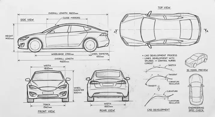
Automotive design involves layered processes. You usually start with a 2D drawing, typically a side view. Then, you refine the drawing in CAD using splines and control points. It’s crucial for the lines to be smooth because that calls for the use of tangent and curvature regulators. Once everything is ready, the outline can be converted into a 3D model, and a top view of the drawing can be obtained to ensure it meets the engineering specifications.
The same principle might be used by beginners too. If you want to try it, lend a hand in a vehicle drawing activity. You should draw the wheels as circles, the body as a closed polyline, and the windows as outlined shapes. Remember to include drawings showing the distance between the wheels and the vehicle’s height.
Need clean 2D CAD drawings? Contact our drafting team today.
CAD File Types and Extensions
Once a drawing is done, you need to save it and send it to someone. Choosing the right format matters. When you share CAD files, the wrong type can break layers, lose dimensions, or fail to open at all. Here are the formats you will see most often in 2D CAD design:
| Extension | Full Name | Best Used For |
| .DWG | AutoCAD Drawing | Native editing in AutoCAD and many other CAD programs |
| .DXF | Drawing Exchange Format | Sharing 2D geometry between different software, CNC, and laser cutting |
| Portable Document Format | Final review, approval, and printing | |
| .DWF | Design Web Format | Lightweight viewing and markups |
| .SVG | Scalable Vector Graphics | Web graphics and simple 2D designs |
| .STEP / .STP | Standard for Exchange of Product Data | Moving 3D models between systems |
| .IGES | Initial Graphics Exchange Specification | Older 3D and surface data exchange |
| .STL | Stereolithography | 3D printing |
Skills Every 2D Designer Needs
Good output comes from good habits and skills. A strong 2D designer or drafter blends technical skill with attention to detail. Key skills include:
- Strong knowledge of one main CAD program
- Understanding of drafting standards and symbols
- Ability to read and mark up drawings
- Good sense of scale and proportion
- Basic knowledge of the trade, such as building codes or machining
- Clear communication with engineers, architects, and clients
- Time management and file organization
Soft skills count too. A drafter who asks the right questions early will save the team hours of rework later.
Common Mistakes in 2D CAD Drawings and How to Avoid Them
Even experienced drafters slip up. Watch out for these common problems:
| Mistake | Why It Hurts | Fix |
| Wrong units or scale | Leads to wrong sizes on site | Set units first and confirm scale in each viewport |
| Messy layers | Hard to edit or share | Use a standard layer naming system |
| Missing dimensions | Builders have to guess | Check each view against a dimension checklist |
| Overlapping or duplicate lines | Cause errors in plotting and CNC cutting | Use Overkill or Cleanup commands |
| Unclear line weights | Makes drawings hard to read | Use a set plot style table |
| No title block info | Confuses versions | Fill in every field before issue |
| Ignoring standards | Triggers rejections and rework | Follow ISO, ASME, or the National CAD Standard |
A simple habit helps most: before you send any file, print it to PDF and read it like the person who will build from it. You will catch problems you missed on screen.
Conclusion
2D drafting may look simple, but it carries a lot of weight. A clean 2D CAD drawing gives everyone on a project the same picture, which cuts mistakes and saves money. You now know what 2D drawing and 2D design mean, how they differ from 3D, which drawing types matter, and which file formats to use.
You also know the standards and habits that separate a good 2D drafting set from a messy one. Start small. Practice with a simple floor plan or a part drawing, follow a layer standard, and check every dimension twice. As your skills grow, the same basics will carry over into 3D, BIM, and beyond. Keep your drawings clear and consistent, and your projects will run much more smoothly.
Frequently Asked Questions
What is 2D CAD drawing used for?
2D CAD drawings are used to create precise flat drawings for building and manufacturing. Common outputs include floor plans, site plans, elevations, sections, shop drawings, and part drawings. Contractors, machinists, and permit offices use them as the main instructions for a job.
Is 2D drafting still relevant with 3D and BIM tools?
Yes. Most permits, shop floors, and job sites still rely on 2D drawings. Even when a team builds a 3D or BIM model, the final sheets are usually 2D views pulled from that model. Knowing 2D drafting is still a must-have skill.
What is the best file format for sharing 2D CAD drawings?
It depends on the goal. Use DWG for editing, DXF for sharing between different programs or sending to CNC machines, and PDF for final review and printing. When in doubt, send both a PDF and a DWG.
How long does it take to learn 2D CAD?
Most beginners can learn the basics, such as lines, layers, dimensions, and printing, in a few weeks of steady practice. Getting good at standards, templates, and speed usually takes several months of real project work.
What is the difference between a 2D drawing and a 2D rendering?
A 2D drawing is a technical document with exact lines, dimensions, and notes. A 2D rendering is a visual version with color, shading, and textures added to help people understand the design. Drawings are for building. Renderings are for presenting.