
Accurate measurement is an essential part of any construction and design project. It must be precise enough so that engineers or constructors can understand the measurements from the drawing and continue the process with a seamless workflow. However, it is challenging to draw a real-world thing accurately and exactly the same size on paper.
For small technical equipment, it works well and can be easily drawn on paper with the same dimensions and calculations. An issue arises when designers are asked to draw accurate drawings of the building or a large and complex project on paper. We can’t fit a building drawing of the same size on the paper to keep the layout clean and legible.
For this, CAD scale factors are used to make the drawing understandable for the engineer to convert the drawing into a real-world drawing. CAD scale factors act as a bridge between the paper drawings and the real-world space.
What are CAD Scale Factors?
When a person hears the term ‘CAD scale factors,’ it may sound intimidating. But in reality, it’s a concept that makes things simpler and easier for constructors and engineers, simplifying life for them by ensuring accurate measurements using scale factors. When designers are supposed to draw the largest or smallest real-world object on paper, that is not possible. That’s where designers need to use scaling that helps them reduce or occasionally enlarge the visual representation of the object while keeping the proportion of the object the same.
Real-Life Example of Using Scale
Let’s look more into this concept using a simple example: a designer is asked to draw a 10-foot-long road on paper. Clearly, this is physically impossible; however, designers use scaling factors to reduce the length in such a way that it can actually fit on the paper without altering the measurements and proportions.
Using Scale Factors in AutoCAD Drawings
When a designer uses the scaling factor in software like AutoCAD, the term scaling factor refers to how the calculated measurements are used digitally for drawings. The system uses proper scaling factors to resize the object so that it can have the same proportion as the real-world object.
This drawing is made with extra care, attention, and with accurate measurements because this is not just a design to exhibit, but it is used as a standard for the constructors and engineers to construct a building. That’s why every minute detail matters because accuracy can prevent significant trouble, shortage, or wastage of material, resulting in a delay in completion time.
AutoCAD software helps designers reduce manual calculation errors and prevent budget overruns caused by slight errors.
Understanding Drawing Scales
Are you trying to learn scaling and how it affects technical drawings? You can’t understand the concept of scaling without understanding what drawing scales are. Both of these concepts work closely together; it is better to understand them first before working on any design drafting project.
Understanding Scale Ratios in Drawings
Typically, drawing scales are expressed in the form of a ratio, such as 1:1, 1:100, or 1:1000. Let’s look into it and find out how to understand the ratios and how they work. Basically, the ratio compares the size of the drawing to the size of the actual object.
Full Scale vs Reduced Scale Drawings
A CAD drawing scale of one-to-one means that the image drawn on the paper is the same size as the real object. It’s called full scale and is used when designers have to draw a small object whose measurements can be drawn on the paper.
The full scale is used for drawing the smaller objects. It’s not practically used for the larger projects like the buildings, roads, and larger instruments and machines. For that, a drawing scale is used as one to fifty or one to one hundred, which means the one unit in the drawing represents fifty or one hundred units of the real-world project.
These scaling measurements vary and are adjusted based on the project size, so designers can draw the project on the screen at the same scale and use it as a construction guide.
Scales Usage in Different Industries
Different industries use different scaling factors to make the drawings. Designers select a scale based on the structure and requirements of the project and what makes the drawing easier to understand at a glance.
Metric vs Architectural Scales
In metrics, the scaling is used as multiples of ten and can be easily understood. But the architectural drawing scale might look different from the metric drawing scale, because it uses scaling in fractions, such as one-quarter inch equals one foot. It might seem difficult to understand at first, but with experience, these scales become intuitive for engineers.
Choosing the Right Scale for a Drawing
The very first thing before starting a drawing is to select the correct drawing scale, because it shows accuracy and helps the reader to understand the drawing clearly. If the smaller scale is chosen, it can make the drawing look so small and difficult to understand. On the other hand, an excessively large scale may result in the drawing exceeding the page boundaries. The idea of maximizing and reducing the size is important because it affects how the drawing will look on the paper or the screen.
How Scale Factors Work in CAD
Understanding how scaling works inside CAD software is very important, especially when working with the AutoCAD scale factor. In AutoCAD, drawings are made and modified using two different spaces: model space and paper space. These spaces work together, but they have altogether different purposes to serve.
Model Space
Model space is where designers make drawings with exact measurements, and no scale factors are used while drawing. The main concern here is to get the accurate measurement of the object, regardless of its eventual appearance on the printed page.
If a wall is 50 meters long, it is drawn with the same measurements in model space. This drawing is specifically prepared for precision.
Paper Space
Paper space is where the drawing is prepared to get it printed on the paper. Selecting the scale range is important in this step. A suitable scale is chosen so that the image fits on the paper and remains legible when printed. This is where scale factors are applied using viewports. A viewport is like a window that shows a part of the model space drawing at a specific scale.
The scale factor in AutoCAD is used inside these viewports to manage the size of the drawing on the paper. The drawing of a building made in model space is displayed using the scale factor of one-to-hundred on the paper space to determine if it fits on the paper or not. These viewports are also used to find the correct scale for the drawing to be portrayed on the drawing space. The drawing does look smaller than the actual size of the building, but the proportions remain accurate.
Annotations such as texts, dimensions, and labels are also portrayed using the same scale in paper space. So that the labels regarding the drawing dimensions are scaled, and do not appear disproportionate when they get printed. One cannot draw accurately without knowing these two spaces.
How to Calculate and Apply CAD Scale Factors
Knowing the CAD scale factor calculation method is important because it helps designers maintain accuracy. The calculation is not difficult; it requires attention to units and measurements.
Step-by-Step Method to Calculate Scale Factor
First, compare the drawing size to the actual object. If the drawing size is ten cm, and in reality its size is 10 metres. Make the measurement units of both sizes the same. If the unit size for the actual object measurement is in cm, then make sure the unit for the drawing measurements is the same as well before starting to calculate the scaling factor.
The formula is:
Scale Factor = Actual Size ÷ Drawing Size
CAD Scale Factor Quick-Reference Table
Unlike the general scale factor calculation, CAD scale factor takes things up a notch. Instead of the drawing size, it deals with the plotted scale numbers. That means the CAD scale factor is the inverse of the plotted scale values.
For a 1/8″ = 1’ – 0’ scale, the scale factor will be 96. If the scale is reduced to 1/4″ = 1′-0″ scale factor also drops down to 48. Here’s a table with different scale factors to help you make an informed decision:
| Drawing Scale | Actual Size (in inches) | CAD Scale Factor |
| 1/16″ = 1′-0″ | 12 | 192 (16×12) |
| 1/8″ = 1′-0″ | 12 | 96 (8×12) |
| 1/4″ = 1′-0″ | 12 | 48 (4×12) |
| 1/2″ = 1′-0″ | 12 | 24 (2×12) |
| 3/4″ = 1′-0″ | 12 | 16 (1.33×12) |
| 1″ = 1′-0″ | 12 | 12 (1×12) |
| 1″ = 10′-0″ | 120 | 120 (10×12) |
| 1″ = 20′-0″ | 240 | 240 (20×12) |
| 1″ = 50′-0″ | 600 | 600 (50×12) |
How Designers Choose Scale Before Drawing
Most designers select the scale first before even starting to draw. The scale selection matters the most to get accurate measurements. For larger objects, a small scale is used, such as one-to-hundred, and for the smaller project, a bigger scale is used, such as one-to-twenty. Different scales are used for the different projects, depending on the size of the paper that’s going to be used at the time of printing.
Important Things to Keep in Mind
There are a few things that need to be considered while calculating the CAD scale factor. Make sure to use the same unit for both of the measurements. Even though the calculation is small and easy on the back end, if not handled with care, it can lead to serious damage and delays in the project. So, it’s important to use the unit consistently throughout the calculation.
Common Mistakes When Using CAD Scale Factors
Most people make mistakes while calculating and using CAD scale factors. It happens because of many reasons, and each will be discussed so that those mistakes can be avoided at the beginning level. When the calculations are wrong, and you start using those calculations as a standard to start constructing the building, it’ll cause a lot of confusion, and builders will be unable to construct the designed project. As the calculation was wrong from the very start, this results in using the wrong scale for converting the model space drawing into the drawing space that fits the paper.
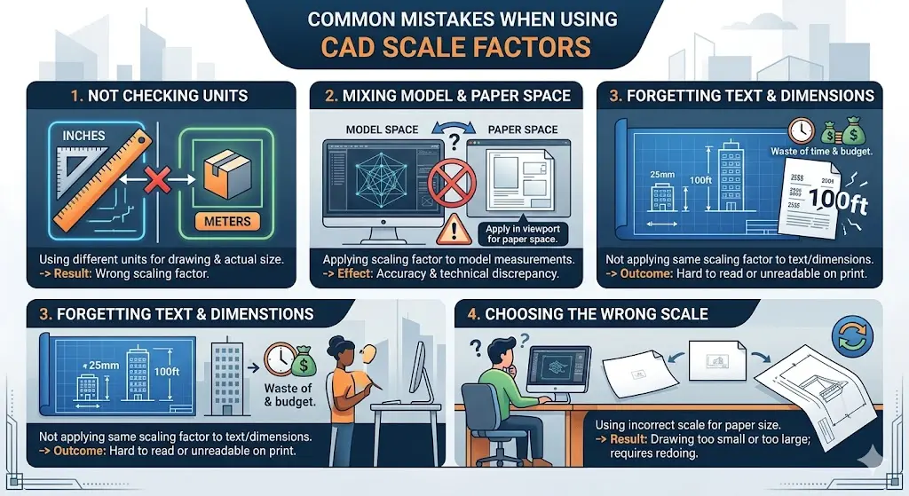
Not Checking Units
One of the most common mistakes that most designers make is not using the same unit for the drawing measurements and the actual size measurements. This results in calculating the wrong scaling factor.
Mixing Model Space and Paper Space
Most of the designers mix the spaces and try to apply the scaling factor to the measurements of the model space. Doing this can affect the accuracy and result in significant technical discrepancies. Make sure that the scaling factor is only applied once the drawing is made in the model space and then, using the viewport, for applying the scaling factor in the drawing space.
Forgetting to Adjust Text and Dimensions
The designer makes sure that everything is handled with care, but there are some errors that at first don’t grab our attention, but later on, they cause trouble. One of the common mistakes is not using the same scaling factor for the text and dimension along with the drawing. When the drawing gets printed on the paper, it gets adjusted, but the text and dimensions are either too small or too big, wasting time and budget.
Choosing the Wrong Scale
Making sure the measurements are accurate and in the last stage, most people use the wrong scale, which either results in printing out a small or large drawing that doesn’t serve its purpose, and requires redoing it, which wastes time.
Architectural Drawing Scales in CAD
Different scales are used for different fields and their designers. It depends on the needs and requirements of the project structure. It makes it easier for the builders and engineers to understand the measurements accurately.
Different Scales for Different Drawings
Different plans support different scales. It’s up to the designers how precisely they select the scale for the project. For a floor plan, the designer selects the small scale because it shows the complete building. Small scale helps the drawing to fit on a single page and makes it easier to understand for the engineers.
Larger Scales for Detailed Drawings
A few project drawings need more details, like the structure, thickness, and design. As for such projects, a large scale is used so the builders can easily notice and measure the small details to focus on a specific part or area. If they are drawn with a small scale, the details may become illegible and end up ruining the design of the project.
Tips for Accurate Scaling in CAD
Professional designers can sometimes make mistakes. Knowing the rules of drawings and calculations, and knowledge about different spaces, is not enough. What matters the most is how carefully you use different spaces and do the calculations. Even a slight error can cause serious issues within the project.
Use the Same Unit Everywhere
Make sure that you are using the same unit when calculating the scaling factor. Because measurements done using the different units can result in a huge difference, and become a cause of wastage of material, time, and money.
Check Before You Print
No matter how carefully you work on each step of drawing, it’s natural for a human to forget things or miscalculate, so it’s better to verify the details and measurements before getting it printed on the paper.
Use Standard Scales
It’s preferred to use the standard scale while making drawings and doing calculations. Because it makes it easier for the constructor to understand the standard terms more easily than the customized ones, it’s convenient to use when multiple people are working on the same project; they all must understand the measurements accurately without misunderstanding anything.
Create and Use Templates
Using templates can save a lot of time and prevent any errors. Set your own scales, text sizes, and layout in advance, and can use that for future projects. This way, you don’t have to set everything up again and again, and it increases the chance of making errors.
Ready to design with absolute precision?.
Conclusion
In the complete process of CAD drafting services, one might think scaling is just a small and easy step among all the processes. But it carries a lot of importance in the overall process. No matter how accurately you have prepared a drawing, if the scaling part goes wrong, it ruins the complete design and delays the construction process. Without a precisely done scaling, a well-structured drawing can become confusing for the builders and engineers.
Scaling is important for almost every project because it helps the designers to resize their drawings so that they can fit on the paper without changing the actual real-life object proportions. In order to get the best results, one must understand how to make use of different layouts, models, and units. While finishing a project on schedule is important, delivering a drawing with precise calculations and scaling is the true mark of a professional.
FAQs
What are scale factors?
Scale factors help engineers and constructors to understand the drawing in a better way. It tells how much the size of the drawing is reduced and enlarged to make it fit on the paper without changing the proportions.
How to calculate the scale factor?
Ratio is used to write the scaling calculation of the actual and the drawing of the object. In order to calculate the ratio, divide the actual size by the size.
What is the scale factor in geometry?
Scale factor is the number that is used to increase or minimize the size of the drawing in geometry, while ensuring that resizing won’t affect the proportions.
How to scale drawings in CAD?
You can scale a drawing by adjusting viewports in paper space for printing. Make sure to use the scaling factor in the paper space and not in the model space.